Saturday, 28 February 2026

The Iomega Zip 250 in 2026

Recently, I wrote about getting a floppy drive up and running in order to get some data from an old 3.5" disk and lamented how difficult this was at the present time.

Well, this time around, I am doing the same thing, but for an Iomega Zip 250. I have a bunch of Zip disks that have data on them that need to be archived as well as some zip disks I used myself around 20 years ago. 

Zip drives were an interesting phenomenon that occurred during the late 90's and early 00's. They came at a time when we didn't have USB drives and high storage portable drives didn't exist. The only choice for storing large amounts of data at that time were on CD-R or CD-RW. Other than that, we we restricted to the 3.5" floppy and its 1.44MB of storage. 

And these were limitations the peripheral industry were keen to break through at the time. One of the ways that these limitations were challenged was through the introduction of "superfloppy" drives. A number of different companies released their own take on the super floppy concept and the Zip series was Iomega's contribution to computing history. And it was a pretty significant one, a lot of people who used computers back in the late 90's and early 00's will probably remember the bright blue devices, which is probably one of the reasons the colour was chosen. When I was looking up information on the devices for this article, I also discovered that the format saw a lot of support in the music industry, with many devices supporting them as a storage medium. The brand was so successful that it was even co opted for the Clik! drive, which was branded as a Pocket Zip at some point. I have actually had a Clik! drive for years, and have never used it due to its interface. If I ever manage to get something that could let me get it up and running, then it would definitely be an obsolete media I would describe...

I have no idea how to get this working...

Unlike a lot of its contemporary's, the Zip drive itself was often sold as a portable solution, if you considered a cable, separate power supply and drive to be portable by todays standards... But back then, this was entirely something you could move around easily. When I think back to the time this device was first introduced, I remember seeing the parallel port version than anything else. In fact, when I first saw an internal drive fitted to a PC, I was surprised.

a typical Zip disk

But, given that portability and compatibility was one of this products selling points, there were many different connectivity options ranging from IDE to FireWire.

There are three versions of the Zip drive, the 100, 250 and 750. The numbers refer to the storage capacity they supported which ranged from 100MB to 750MB, with each iteration of disk being roughly the same size as a regular 3.5" floppy. Each new generation could read from the previous iterations media, but could not write back to them. In fact, the 100 model has a rather interesting mechanism for detecting licensed media that seems to use optical sensors.

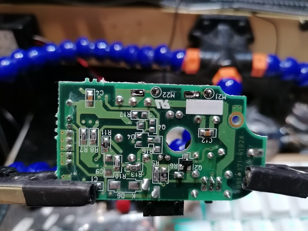
the optical device used for detecting media

As I didn't have a drive any more, I had to resort to eBay in order to get started. I was able to get a hold of what was described as an internal version with a USB connection. It was dirt cheap, however when it arrived the drive itself was almost pancaked - the seller had decided to wrap one, thin layer of bubble wrap around it. This required me to repair the bezel by gluing it back together and bending the metal part of the case back into shape.

bezel is worn, but it is hard to see that it was smashed

Also, the USB connection was a bit of a white lie. It was an IDE to USB converter from an old external USB hard drive enclosure, specifically a Freecom device. Sadly, the interface didn't work even when powered up and connected.

It turned out what I had actually bought was an internal ATAPI model, which I didn't think was going to be much of a problem - until I started to search for an IDE to USB connection.

the interface formerly known as EIDE

After searching high and low for one, I took inspiration from my eBay seller - who actually refunded my purchase after I told them about the delivery issue, which was very nice of them. I started looking for an external IDE hard drive to USB enclosure, even these are not easy to find these days. Once I had my hands on one, I just gutted it for the interface and hooked it up to the drive.

the loom running to the front is a power switch

With the interface connected and powered on, nothing actually happened. It was only when I inserted a disk did the drive appear in Explorer, and even then it didn't appear as a Zip Drive. Instead, it appeared as a removeable drive.

This is probably down to the fact that I used an interface from an external HDD enclosure. Or maybe it is because there are no Windows 11 drivers? Not sure, but what we have is a working Zip Drive that will read 100MB disks and read/write 250MB disks over USB 1.1 connection.

But, and this could be a significant but, if you have any old Zip disks that you would like to use again that have been write protected, then you wont be able to undo this.

This is because the Iomega software simply doesnt work on Windows 11. You might be able to install it, but for me it didn't happen. And the reason for this? The software, IomegaWare, doesnt support 64bit operating systems, you will need to use a 32bit operating system to get this done. Specifically, it is due to an incompatibility with version.dll across 32 and 64bit platforms, one that wont be fixed. So this means trying to install it in compatibility mode on a 64bit operating system will not work.

It isnt just this software that is effected, there is a lot of 32bit software that suffers as a result of this incompatibility, which some might call a bug.

In order to access these disks, you are going to have to jump through some hoops. So lets describe the problem first:

You need to use the Iomega software in order to remove the write protection on your disks, but it wont work on your OS. So, you need an OS that the software works on, you either want to use Windows XP or Windows 7. Compatibility mode wont work - you need to be using one of those environments.

I didn't include Vista, because I really didn't enjoy Vista.

Maybe you have an old machine that you can install Windows XP or 7 on. If you do, then go ahead and get it done and start reading your disks. But, the chances are that you dont have a spare machine that you can do that on that has the relevant connections. If you are doing the same thing as me, then you can get away with a USB connection and an old machine, but we are talking about machines that need to boot using BIOS, not UEFI.

So the next best thing you could do is to create a virtual machine running one of these operating systems, and install the software there. That way, you can pass your Zip drive over to the virtual machine as a peripheral device and work with it that way.

There are a few things to consider here - you cant use Hyper V, which is annoying as you may very well have this available to you. Hyper V doesnt allow you to use USB ports on its virtual machines. So you will need to use another hypervisor like VMWare or Virtual Box. You are also going to need to have a Windows XP or Windows 7 installation disc or ISO.

I am going to assume that the reader has some basic knowledge on how virtualisation works and how to create a virtual machine. So I am just going to go over the steps here quickly, to do this I will be using Virtual Box. This is a free virtualisation solution from Oracle, it is by far from the best one out there - but it is free and will do what we need it to do.

As mentioned above, you are going to need a Windows XP installation and a license code. The best form of installer is an iso, if you have one, or a CD/DVD ROM. For people not used to virtualisation, you are going to need to bear in mind that your virtual machine is going to share resources with your host machine - the machine running your virtual machine. So you might need to be frugal with your allocation of RAM and disk space. Windows XP is going to need at least 4GB of RAM and 64GB of disk space for what is going to be tried out here.

Once you have downloaded and installed Virtual Box, open the application and click on the New icon in the top left corner. This will open the New Virtual Machine window, this is where you can configure all of the relevant parts of your virtual machine. Dont worry if you make a mistake here, you can always come back and change the configuration at any time. Here is a list of the fields, what they mean and how you can use them:

Under Virtual machine name and operating system:

  • VM Name: This is just the name of the virtual machine. Here I just used "Obsolete Media"
  • VM Folder: This is the path where the virtual machines files will be saved. These will take up quite a lot of space. If you configure a 128GB disk for your virtual machine, then its files will be at least 128GB in size, so you need to make sure that your disk has enough space. I have a specific location for virtual machines on my dev box
  • ISO Image: This is the file you will use for installing Windows. Select it here, it is only going to be used once when creating the machine.
  • Proceed with Unattended Installation: Tick this to have an almost silent installation.

Under Set up unattended guest OS installation:

  • Username: This is the name of the account the setup will create for you, I changed this to user.
  • Password: This is the password for the account you are creating.
  • Product Key: Enter your Windows 7 license key here.
  • Install Guest Additions: This will install all of the enhancements available for Windows XP under Virtual Box. I recommend choosing this option.

Under Specify virtual hardware:

  • Base Memory: This is where you set the amount of RAM your virtual machine will use. I recommend setting this to 4GB, if you can spare it.
  • Number of CPU's: You can set the number of CPU's your virtual machine will use. You wont need more than one, but if you can spare an extra core, feel free to give it an extra CPU.
  • Use EFI: This tells the virtual machine to boot using UEFI. This is better left unticked for this type of installation. When unticked, the virtual machine will use BIOS during the boot process.
  • Under Create a New Virtual Hard Disk:
  • Disk Size: You can use the slider or the text box to set the disk size here, you can leave it at the recommended setting, but I advise setting this at 64GB if you can spare the disk space.
  • Hard Disk File Type and Format: You can use this to make your virtual machine compatible with other hypervisors. Leave this at its default.
  • Pre-allocate full size: Ticking this will cause Virtual Box to bump the virtual hard disk file size up to its maximum amount. So, if you have a 64GB disk, a 64GB file will be created. Unticked, the disk file will increase as your virtual machine will expand the file as you store more data on it.
  • Split Disks into 2GB Parts. This will cause the hard disk file to be split across multiple 2GB files.
  • Use an Existing Virtual Hard Disk File: This allows you to attach a pre existing virtual disk file to your virtual machine. This is how you can move virtual machines across hypervisors.
  • Create a Virtual Machine Without a Virtual Hard Disk: This allows you to exactly that, create a diskless VM.

With all of your config set, just click on finish. This will cause your virtual machine to power on and the Windows installation process should start automatically. This will take a little while, despite the speed of your machine. My dev box is an i9 with 64GB of RAM, but it takes almost an hour to install Windows XP on Virtual Box. HyperV  takes minutes...

Whilst that takes place, you can go ahead and download the Iomega software and drivers for the Zip drive, which have been handily preserved on the Internet Archive here. It is an iso, so you are going to need to extract the contents before you can use it on your Windows 7 virtual machine. You can do this by simply opening it under Windows 11 and copying all of the files to a location on the Windows XP virtual machine.

I moved the files over using my network - however, older operating systems like Windows XP dont support file sharing services used by Windows 11 etc. To do this, you will need to turn on SMB 1.0 file sharing on your host machine. You can turn this feature on by going to System -> Optional Features -> More Windows Features and selecting SMB1.0/CIFS File Sharing Support. This will force a restart, but once you are back, you will be able to share a folder with your Windows XP virtual machine.

The file that kicks everything off is called setup, and it launches a wonderfully old fashioned installation process. There is nothing about the process that is particularly tricky, it is basically an extended EULA agreement, however at the end you will be asked if you want to shut the machine down, the best thing to do here is to say yes. This is effectively the end of the installation process, all that remains to be done is to connect the device and start the virtual machine up - wait until the drive has finished installing on the host machine first, this will be the first indicator that something can be wrong.

If you encounter any issues during the installation, or you dont get the screen asking you to shutdown the machine, or you get an error mentioning GetFileVersionInfoSizeA, then you are likely running a 64bit version of Windows.

Once your host machine has finished off installing the drive, you can now pass the device over to your virtual machine. You can do this from the window the virtual machine is running in by going up to devices and then USB. Here, you will see all of the USB devices currently connected to your host machine. If you are not sure which one is the one you want to pass over, disconnect it and see which one disappears from the list - this is the device you want. Just click on the device to pass it over to your virtual machine, as soon as you do the operating system will start to install it.


If you dont encounter any errors, then you are in for a very anti-climatic finish. IomegaWare doesnt install a front end, just a set of shell extensions that can be used on Iomega drives. Once Windows has detected and installed your drive, you should be able to right click it and see the tools that IomegaWare provides. Specifically the most useful one - Protect.

This is the tool that provides the protection layer through software. With the suspect disk in the drive, right click the drive and select Protect. From here you will be able to remove all of the write protection from the drive itself and then format it.

the fruits of my labour

However, if you are following along with this and you have a disk that is not protected, but keeps asking to be formatted - then that disk is probably dead. I had one disk out of 20 that displayed this behaviour. If that is the disk you wanted to get data from, dont throw it away. This is probably as far as I am going with this drive on Windows, but when I was browsing the files on the IomegaWare install disk, I discovered a folder that contained Linux drivers.

So it may be the case that when using a 32bit Linux, I may be able to resurrect my dead disk - or even use some recovery software on it to see if there was anything interesting on it at some point. It is definitely something that warrants a little investigation.

And thus concludes the rather convoluted tale of how I got another obsolete medium working on modern hardware in order to get some files I created 24 years ago.

Was it the best way to do it? Probably yes, I think? It was one of the cheapest ways of getting a drive, which turned out to be essentially free in the end. was my connectivity choice correct? Well, I could have held out looking for an external USB model, but then I would have ended up paying out way too much than I would have liked. The external USB enclosure I bought for this, even when added on to the cost of the Zip drive wouldn't have been close to an external USB model. This wasnt a particularly tricky way to connect a drive to a machine, but in its present state, it is something you would only use when you needed it, like the floppy drive, it requires an external encloser. That or to be installed in a case, but what cases come with external drive bays these days?

I think they key part of this work was getting the software installed and working. Getting old disks unprotected and formatted is without a doubt the most useful thing I have been able to demonstrate here. It opens up possibilities for anyone using retro kit that employs these disks and drives and isnt that hard to do - the trickiest part is getting the virtual machine up and running with the software. So even if I had chosen to get one of the external models, the same amount of effort would have been required.

The next thing I will be looking at is another super floppy, in the form of an LS-120 - and I will definitely take a look and see what it would take to get that Clik! drive running...

Wednesday, 25 February 2026

Floppy Disk Drives in 2026

Recently, I have needed to get some data from a set of old 3.5" floppy disks - and I learned that getting this done easily in 2026 is no mean feat.

I naively thought that something as ubiquitous as the humble floppy drive would never become abandoned technology and assumed that I could hook one of the many drives I have up to at least one of my machines. This wasnt the case, not one of my machines had the relevant connector that would allow me to connect a floppy drive.

This shouldn't have been a big deal, I thought to myself, I can just get a external USB floppy and use that. However getting one that works under Windows 11 wasnt so easy. I ended up getting an Iomega 3.5" floppy and memory card reader combo device which would work if I used a specific driver - but getting it to work consistently was an issue.

OK, that was a bust, so how about a 3.5" to USB converter? They turned out even harder to find, however there is one solution that is quite readily available. It requires a bit of work to get it going, it isnt for the faint of heart, and there are probably far better solutions - but this is the rabbit hole I ended up going down.

It is essentially a two part 3.5" to USB converter that is connected by a 26 pin ribbon cable. Typically, you will not see both parts sold together, so many people will pass this by as they wont see how to use it. In fact, the only other source of information I found about these was another blog post that lamented the connectivity.

Another thing that will make people pass on this is the fact that the USB connection is not readily obvious. It doesnt use a standard connector, so you will need to source the correct connector type and crimps before you can even think about hooking it up.

In fact, if you are on this blog right now, it may very well be that you have these devices and want to know how I got them working, or you are researching about how they work before you go ahead and buy them for yourself.

This is how I got them up and running for me to get a simple 3.5" floppy drive connected.

The drive I am working with is a simple Sony MPF-920, which seems to have a date code from April 2006. I dont remember where it came from, but I know it was tested and working.

A suitably old floppy drive

The next part to look at is the USB connection. The board is marked as a UF001F, if you run that through Google you will get loads of hits, however the cheapest prices will nearly always be on AliExpress, an example can be found here.

Note the non-standard USB connection on the left

It is important to note where pin 1 is on this board as it is not clearly marked. It is the pin nearest the USB connection.

I got this information from the Electronics and Repair blog who posted an article about this device. 

As I mentioned above, they seem to be the only other place on the Internet that has posted any relevant information about any of these devices. Not only do they identify pin one on UF001F, they also describe a complete pinout for that board.

Please go over there and take a look at their articles, they publish some really interesting things.


The next part is the 3.5" interface. This plugs directly into the floppy drive interface and exposes a 26 pin ribbon connector and a standard floppy drive power connector. This is because the completed setup will attempt to supply power to the floppy drive via the USB connection. This isnt required, however, if you are supplying a separate source of power, for instance from an ATX power source.

This board is marked as an ELS@26-34, searching for this will again bring a large number of results and prices, but the cheapest are once more to be found on AliExpress and sites like that. An example of one can be found here.

Pin 1 is clearly marked on my board as can be seen. It doesnt seem to be different on the other boards I have seen for sale so far.


All you need to connect the two parts of this adapter together is a 26 pin FPC ribbon connector with a 1.0mm pitch. Getting a longer one may be better than a shorter one, you can get bags of these from Amazon for a few pounds, the ones I got were here. Comically, they were packed in a veggy bag from the supermarket and then sealed in a cardboard box...

all those alphanumerics mean 26 pin, 1.0mm pitch...

As I have kept eluding to, the USB connectors on these boards are kind of none standard. If you have spent any time inside a laptop, then you will recognise them straight away, but probably be unable to put a name to them. Plus, you still have to attach a standard USB connection.

I found the correct connectors on DigiKey, and purchased some pre-crimped leads along with them - I hate crimping at the best of times and had no patience in my life to crimp anything this small. The connections are clearly marked on the UF001F for USB, so doing this part of the hook up is relatively easy. I ordered the longest pre-crimped cables they had in stock, they are crimped on both ends, so cutting them in half doubles the amount of leads I have to work with.

Be carful when stripping wire that gets as thin as this, you might end up just cutting straight through it, ahem...

The connector type itself is a JST ZH series connector, specifically a four pin connector.

To make the other end of the USB connection easy, I bought some USB ports from Amazon that have all of the connections marked. Then I simple connected my new lead to these connections - this now means all I have to do is hook it up with a USB to USB micro lead to use it.

these are 5 pin micro USB ports

You need to get either 4 or 5 pin versions of these ports - dont confuse them with the far cheaper power only ports that wont work for this build. As you will see from the image above, I have actually obtained the 5 pin type, the fifth pin is badly identified on these boards, but it should be labelled as ID. This port is used to switch the connection from host to peripheral.

A quick explanation on this; the easiest way to explain what a host connection is would be to compare it to your computer. When you insert a USB device, the computer controls how it is used. This is a host connection.

Whereas when you plug a USB drive into a computer, the drive is not in control of the connection or interaction. This is a peripheral connection.

I dont need a host connection at all, I want the finished device to be on a peripheral connection.

To achieve this, I do absolutely nothing. When the ID pin is kept open, it means the USB connection should be in peripheral mode. 

Grounding this this pin would put the USB connection into host mode. Whilst inapplicable for a floppy drive, it would be useful if this was on a phone and a USB drive connected. This would allow you to browse the contents of the drive.

However, I just dont need a host connection. This is just going to be a regular USB device that I attach when needed, so I am leaving this pin open to configure it as a peripheral device.

If you want to know more about USB and its technical specifications etc, then the very best place to start is Wikipedia. It gives a good explanation for people who dont know much about it beyond using it and contains all the links to take you on to the technical documentation. But for this build, we dont need to go into any further detail.

an ugly, but functional USB lead with a background of messy desk

With all the parts of the device connected and with the appropriate interface attached so we can hook it up to a host device. But before we do that, I need to carry out some basic tests. Firstly, I need to check that the USB interface is hooked up correctly to the USB port. With the ribbon cable removed from this part of the device, I can attach this to my computer and check to see if the interface is detected and installed.

the entire thing connected

Windows should detect the connection and install the hardware it has just seen. Next, I need to disconnect from the computer and reassemble the entire device - this is the point at which we test the finished build.

Windows should detect the floppy drive after a short delay - if you have been following this article along and your floppy drive doesnt appear in Explorer, just pop in a disk. The drive should start reading the disk straight away and appear in Explorer.

If you go and check in Device Manager, you can confirm two things; that a a USB floppy controller and a floppy drive itself has been installed:

you should see a USB floppy controller installed

It seems to show up as a TEAC drive regardless of the drive you are actually installing.

you should also see a floppy drive installed

One odd behaviour I noticed here once everything was connected up is that the drive activity light was on all of the time, even when there was no disk in the drive.

Also, the drive really complained when trying to read a disk. This could be down to a number of different things, I went through an entire box of disks when testing this drive. It could read all of them apart from one, which I know was used up until quite recently. So it could be down to the media itself, also a large number of these disks could have been formatted for other systems, and Windows 11 doesnt seem to be able to trigger an error. However, it read a disk that was formatted on Windows XP and last used in the late 00's read fine.

So this could be down to a file system issue?

There is the fact that the interface itself identifies itself as being made by TEAC, the drive itself is made by Sony - so there could be a compatibility issue in play here. That is something I can test by getting hold of a TEAC drive, which I think I might have..

But, if the drive doesnt not spin up when you insert a disk it means you have one of a number of problems:

  • Your drive doesnt work. See if you can test it out in another machine, if at all possible. I know that if you are reading this then that might be harder than it sounds...
  • You have reversed the connections with the ribbon cable. This could potentially damage the drive and the 3.5" interface so it makes a lot of sense to ensure you get the right pins connected.
  • Your USB connection isnt working. Change the USB lead if it is inconsistent, then check the solder joints on the USB port. Also, check the cables on the USB connector on the USB interface.
    • This actually happened to me when I was testing my connection. My USB 2.0 ports didn't work with this device. It only started working on my USB 3.0 ports on that machine.
  • You are not supplying enough power to the floppy drive. The power for the drive is supplied by the USB connection. Depending on what you are connecting to, you may not be getting enough power over the connection to allow the drive to function. To resolve this, provide a separate power supply, it only requires 5 volts.

And fantastically, I have a working USB to floppy interface. And even this was easier than getting an IDE to USB interface working... Obviously with some caveats...

Finishing up, there are some considerations that need to be noted about what I have done here. Firstly, this is a long string of devices held together with different connectors. It isnt something that I can just have out on the desk forever, it would just get damaged.

This is a build that will require some sort of enclosure to hold it for the long term, and one that has enough space to have all of the components used above to fit in. If you have experience with 3D printing, then it shouldn't be hard for you to knock one out pretty quickly. Or, you could repurpose another enclosure to serve as its home. But, bear in mind that you may need to provide a supplementary power supply.

And that leads me on to the second issue - power. If you are planning on running this from a USB hub, then you may find out that you simply dont have enough power going to the device. The drive I am using states it requires 5 volts DC and 950 mA, that is not a small amount of power when we are talking about USB. 

You may want to consider making your own 5 volt power supply, or consider using an ITX power supply. If you are feeling even more ambitious with your build, why not an ATX power supply? The choice is yours, all you need to do is source some floppy drive Molex connectors. Whatever you choose to do, make sure it is the safest choice, please dont go trying to make your own wall charger or anything like that. 

Personally, I think using something like an ITX power supply is one of the best ways to go. They are small, safe and they provide all of the connections you need.

Lastly, this is a basic floppy solution. It may not provide the full functionality of a floppy host controller that you would normally find on a motherboard. It struggles to read disks that shouldn't be giving it issues. If you are a technician, then this isnt the solution for you, there are better solutions out there which I will be taking a look at in the very near future. If you are looking for a simple USB floppy solution, then this isnt for you either. It is fiddly, requires some basic soldering skills and needs you to get components from multiple sources.

I could only really recommend this to someone who is investigating the idea of building their own USB floppy drive and wanted to understand (some of) the capabilities of the components they are using. Or perhaps someone who is interested in adding a floppy drive to a single board computer like the Raspberry Pi.

Something tells me that this wont be the last time I take a look at floppy drives... When I was researching the potential solutions for this, there are a plethora of even more technical solutions that would have taken me even further down the rabbit hole - there are even alternate solutions to the humble floppy drive itself.

However the next thing I will be looking at is a similar issue with the legendary Zip drive from Iomega. I have a similar problem to solve there - going from an older interface to USB.

But - did I manage to get the data from the disk I was working on? The answer is yes, I did. Plus a lot more from the disks I used for testing. None were labelled, so I was pleasantly surprised when I found some Acorn software on them :)

Friday, 18 November 2022

Replacing the CMOS Battery in the Acorn A7000+

 Last time, whilst I was waiting for some Game Gear parts to arrive, I decided to take a look at my A7000+. I learned that it was getting on a bit and was in a poor way. The CMOS battery had failed in a dramatic manner and leaked across the motherboard, we left the previous post with the battery removed and the board cleaned up for the next step, but before we do anything else, there are a couple of jobs that we need to take care of first.

Some of the gunk from the battery covered the legs of the IC's in the effected area, one of these IC's is the CMOS memory itself. Whilst I took care with cleaning this area up, trying not to break traces or legs etc, there still may be some damage in a different layer of the board. So I needed to make sure we had continuity between the CMOS memory and the battery terminals. We also need to make sure that the battery terminals have continuity with the power bus on the motherboard. This is the easiest thing to test, so we can start with this, simply use the multimeter to test the positive and negative terminals against any ground or + voltage connection on the motherboard itself.

The first test passed fine, so to test further I would need to test the battery terminals against the CMOS memory's VDD and Ground pins. The memory installed on my A7000+ is marked as an 8583T, when researching this product code, I discovered a datasheet from 1997, which would have been contemporary for this machine. The datasheet is available from here and gives us a wonderful amount of information on what this part does and most importantly, it gives us the pin out.

The IC is described as a clock/calendar with 8-bit RAM. This makes sense, because near to its location, there is a 24Mhz clock. Interestingly, this IC also has an I2C interface, so you could hook an Arduino or Pico or even an ATTiny85 to one of these... The datasheet also advises us that the IC has an operating voltage of 1 - 6 volts, this is useful information when it comes to replacing the old battery. And in there it gives us the pin out. We are going to be testing two specific pins here, pin 8 - VDD against the positive battery terminal and pin 4 - VSS against the negative battery terminal.


It passed the test fine, so I know I have a good connection from the battery to the motherboards power bus and from the battery to the CMOS memory. I also know that this is, at the very least, the system's real time, or RTC, clock with an operating voltage of between 1 and 6 volts. This is important because I know that the battery can be at least recharged by the motherboards power bus, if the battery and motherboard are compatible with regards to charging. I also now know that the battery is capable of providing power to the power lines for the CMOS memory, which means if the battery has a charge, it can provide power to this IC when the main power is off.

All I needed to do now is find out about the battery that I removed. Frustratingly there is almost no official information on the factory installed battery, and reading any information from my battery was out of the question due to the amount of corrosion present. I tried scraping some of it off, but it resulted in too much damage to the surface. 

Whilst I was going about these tests, a member of one of the Acorn groups I am in on Facebook asked if I could check the connectivity between the SoC and the CMOS memory. Basically to confirm which pins were used for I2C from the SOC to this IC. His reason for this was quite interesting, he had a Bush IBX board, which is the guts of a smart TV box from a few years back, Apparently, these are cut down versions of the A7000/7000+. Modifying them to have the same CMOS functionality is part of the process of getting them to run RISC OS, its quite an interesting process and if I get my hands on one of those boards, it will definitely be something I will try out. I saw the end result of his efforts posted in the group recently and he had managed to get RISC OS 3.71 installed and running on it, which I think is pretty cool.

One of the things I wanted to address with the battery was could I use a battery of a different voltage, and could I use a battery of a different type? The battery that is normally installed on these machines is a Varta 280H or sometimes 300H NiMh 1.2 volt rechargeable cell with a capacity between 250 - 300 mAh. This is the component that was physically soldered to the board. Here it is still attached to the board:


I know that the CMOS RAM has an operating voltage of between 1 and 6 volts, so I know I can replace the damaged battery with another one that is between this range with a similar capacity. The next thing I wanted to find out is if I could swap from using a NiMh battery to a LiPo. After doing a lot of searching I discovered that the first Li-Ion batteries went on sale in 1991, which was only six years before this machine was made. After asking a few questions here and there it became apparent that no, I couldn't use a LiPo due to the fact the motherboard has no way to recharge the battery. I would need to provide the electronics for such a battery to do this safely and ensure it would work with the existing logic.

Naturally, I chose to use a NiMh instead.

As a complete stroke of luck, I happened to have the exact battery I needed for this to work. I was stunned to the point that I needed to take a moment and have an energy drink - so far I have embarked on a project and I just happen to have all the things I need to do what I need to do without ordering things in. Surely something is going to go wrong soon? The only difference being that the replacement battery was physically completely different, in the AA format, but thats OK.

Checking the battery over made sure that it put out something in the region of 1.2 volts and I set myself to learning why a NiMh is the easiest choice for this application. It turns out, according to Wikipedia, that NiMh batteries can trickle charge when connected to a power source over time. However, they cannot be used as they are being charged, and it takes time for them to charge up. My battery was almost fully charged, I think it came out of a solar powered light that I took the solar panel out of and just kept the battery next to my keyboard, so it is pretty new with almost no charge cycles. I also learned why having a battery with a higher voltage would have been a bad solution.

Because the battery installed on the motherboard would be trickle charging, it would take quite a long time for it to be available to the CMOS memory. If, for example, we had five of them connected together for 6 volts, it would take a lot longer for them to charge completely. Which means that the battery would not be available to the CMOS memory for a lot longer than it would take to charge a 1.2 volt battery.

This means that when you power off the machine, you lose your clock. You would need to reset the clock each time your turned on the machine and save that to CMOS until your battery pack had fully charged.

So keeping it broadly the same as the original part is the best course of action here. All I need to do is connect the AA battery to the relevant terminals and we are golden. But, before we do, lets address one of the design oversights with this board - the battery placement.

NiMh batteries like to leak, pretty much every AA battery I have come across in the last couple of weeks likes to leak, and when they do it can be a disaster. So connecting this battery directory to the board is a bad idea. So lets add a lead with a connector to the board, so we can move the battery away from it, reducing the ability to cause damage in the future.

We are going to solder a lead into the battery terminals that were exposed after removing the damaged part. The top two are marked as positive, red - you dont need to connect both of these to positive, one will do. But if you want you can fly a connection over between the two. Use the square pad to help you keep track of what you are doing. The single terminal on the opposite side is for negative, black. To keep things neat, you might want to poke the wires through the top of the board and solder from below.

Once soldered, we have a connector that takes us all the way to the edge of the motherboard:

Now that part is sorted, I need to take care of a battery holder or retainer. I had a go at making my own with some perf boards and some spare battery terminals that I was hoping to use on the Game Gear, but I wasnt happy with the result, so will keep that for prototyping. Instead, when looking through a box of potential stuff, I found some fairy lights that were powered by two AA batteries in a little enclosure. This was perfect for what I needed.


Removing the switch and single spring terminal gave me the basis to create a single AA battery holder. This also had a switch installed, which was also removed. The unused side of the battery enclosure was used to run a wire down to the double terminal. An opposing connector was added to the newly installed leads and I once again tested the output voltage to make sure it was OK. With the length of wire between the two new leads, I have quite a lot of flexibility when it comes to hiding this box in the case.


Now, what I really wanted to do was plug it straight in and see if it worked. But - this machine hadn't been turned on for a few years, and there had been damage to the board that I needed to clean up. Plus, I didn't know if having a completely wiped CMOS memory was a good thing at this point or what hitting it with 1.2 volts was going to do to it beyond the control of the motherboard. I also didn't just want to plug the PSU in and fire the mains up either without checking to make sure that the PSU was putting out the correct voltages etc - there was still a bit of testing to do, but as of right now I have almost achieved my goal...

But what I can do is install the battery holder in the chassis somewhere out of the way. 


Using a single command strip, the battery case is held in its new spot, tucked away from anything it might hurt if a battery might go pop in the future. I think using a closed battery case will also help prevent any potential damage in the future.

Next up, we need to get started on testing the power supply and see if this is going to cause an explosion with my new battery...

Friday, 11 November 2022

Looking at the Acorn A7000+ in 2022

 Back in 2010, I made a little post about my Acorn A7000+, where I mentioned my past experiences with the machine and its OS.

The other day, I thought to myself that I should get it down and get it powered on again in order to try some things out with DNS. Before pumping mains electricity through it, I thought it would be a great idea for me to take a look inside it because it hadn't been powered on for about four years.

And I am glad I did.

During that four year break, the CMOS battery attached to the board decided to leak and its contents were deposited on the board itself. This requires me to replace the battery and repair the damaged area, This is the story of how I achieved this.

The A7000 and the A7000+ are very compact machines for their period. Despite the outward appearance of the case, which is only really that large due to Acorn recognising that a CD drive would be used at some point, the system itself is quite small and has a remarkably low profile. I am not sure if Acorn had different hardware options in mind when they designed the board etc, but I do know that this design made its way in to a lot of set top boxes.

The low profile is achieved, in part, due to the use of passive cooling - no heatsink or fan is on the CPU here, which is in stark contrast to the time in which this article was written. At the present time, heatsinks and fans can be quite large, and water cooling solutions are becoming more popular. When this machine was made, not having a fan was still something that happened - but more and more systems were getting fans installed at the factory.

The CPU in the A7000+, the machine I have, is probably better being described as being an SoC. I found the datasheet for it here. The main areas it controls are as follows:


This makes the layout on the motherboard quite clean and uncluttered and allows for it to be as small as it is.

This model also provides two methods for expansion in the form of a backplane connector for a hardware format named "podule" by Acorn and a standard internal network connector that is compatible with past Archimedes models. Sadly, Acorn didn't think that networking was going to be such a big deal for their ecosystem, in my opinion, at least. I think it has always remained an after thought.

For the backplane connector, I dont really remember much being commercially available for it at the time. However, these days there are quite a lot of things that are available to buy or to build yourself, including USB interfaces and GoTek interfaces. Sadly, due to the design of the board, you cannot use a CD drive and the backplane interface at the same time. I think this was an oversight and the main reason why I didn't see many expansions for it. These machines were intended to be used in schools, and schools were always going to go for media rich CD ROM based software over an expansion card.

The network cards were useful though, a lot of them at the time supported both Ethernet and BNC, which was really useful. But they were expensive, and to the best of my knowledge still are. The one I have now is just Ethernet, but works perfectly well on my network.

As standard, the A7000+ came with 8MB of RAM from the factory soldered to the board. It also had one memory expansion slot for a SIMM - anyone remember them? They were the bane of PC owners lives, tantalising us with their ever lowering prices. Always knowing that we would have to buy two of them at a time. However, the A7000+ didn't have that drawback, you just needed one to increase the available memory, and could support up to 128 MB, it also supported EDO RAM as well as FPM. This was a pretty big deal back then, EDO was the fast RAM that the cool gamers would have in their systems.

When it came to storage, it came with a 3.5" floppy drive as standard - the mere thought of not having one of these was pure ridiculous, and an IDE hard disc. I think there were various SKU's offering different amounts of HDD space and expanded memory, as well as with a CD drive option. Mine had come from a school, and still has the factory HDD, but the CD drive currently installed is mine (it just happens to be the first ever CD burner I ever owned...). One of the interesting things about RISC OS, at least up to 4.02, is that you have to tell the OS if you have a particular type of drive installed. It doesnt seem to be able to auto-detect them in the same way that a lot of contemporary x86 based desktops would have been able to.

Other than the network port, the A7000+ also has one DB9 RS-232 serial port and one printer port. It also has a PS/2 port for the keyboard and mouse separately. Another one of the oddities with RISC OS is its dependency on having a three button mouse. Annoyingly, the context menu appears on a middle click in this OS as opposed to a right click in Windows. At the time, PS/2 mice with a scroll wheel were still not ubiquitous. Whilst we cannot imagine a mouse not having a wheel now, there were still a lot of places that didn't automatically get wheel mice as soon as they became available, these places include offices and schools who typically only replaced mice as they broke. So if you didn't have an Acorn mouse, or it broke and you couldn't get a replacement, you might have been in quite a pickle. It happened to me when I was testing the machine out later on.

One really quirky feature of RISC OS that, quite frankly, annoys me, is that you need to define a monitor configuration in order to take best advantage of its video capabilities. To this day, I am not really quite sure why you have to do this, naturally all of the relevant Acorn monitors are supported and I have seen them in action. So I know how wonderful the OS can look, and at the time this has to have been the best looking OS on the market. You do get a stock 640x480 mode, but you cant change any visual settings. So lets see if we can change that.

Back to the problem at hand, I need to deal with the battery and the damage it might have caused. Opening up the case reveals that the leak has been largely localised to one specific area, covering the case and the board. So I needed to dig the board out from there to start working on the problem. As this meant taking the whole machine apart, I decided to test out the PSU at the same time and replace a bunch of missing screws etc.


With the drive chassis and the drive cables removed, I was able to extract the motherboard from the case. As we are dealing with a battery leak, I am using white vinegar. According to Google and "people on Facebook", this neutralises the acid from the battery and stops further damage? I am willing to believe it without checking it for myself, you can almost see it working at times. I sprayed some vinegar on the effected area in the case and set it to one side whilst I took a look at the motherboard. You can see in the picture that it is localised to one specific area, which is really quite lucky. Also, you can see that the silicon looks amazing for a device this old. This specific area holds the CMOS memory and the Super IO controller for the floppy drive. The battery was here to provide power to the CMOS memory.


After looking at the affected area under a microscope, I realised that the damage may simply be superficial at this stage - which would be very lucky for me. So after carefully cleaning the area with some vinegar and a toothbrush, I was able to remove most of the gunk caused by the leaky battery. With that done, I was able to heat up the iron and remove the battery itself from the board.


I think the quality of the product helped a lot when it came to cleaning up the mess, that and being able to catch it at this stage. After cleaning up from the removal of the battery with some IPA I was left with a nice, clean set of holes for attaching a replacement. Looking at the battery itself, it looks as it one side of it failed, and its guts spilled out.


The negative side was covered in the same crust that was on the motherboard, but the positive side looked almost as if it were brand new. Obviously, the negative side was the one pointing at the rest of the motherboard. There was no chance life would let that one pass by :).

Now that I have removed the cause of the damage, and the superficial damage, I need to replace the battery with an equivalent that is less likely to leak. I should also mount this battery somewhere that, if it does leak, then it would be less likely to cause any damage to any part of the machine. But this post is getting a bit long, so I think a part two is in order.

Monday, 8 August 2022

Repairing the Sega Game Gear - Part 1

The other day I was talking to one of my friends about a drop in screen replacement kit I have for the Atari Lynx 2, something that I hope to cover in a future post, and mentioned how amazing that handheld was. I got around to showing some of the contemporary handhelds that were around at the time, including the Sega Game gear.

Sega were my all time favourite console makers, and when they backed out of the hardware business I almost cried. I have so many good childhood memories playing the Master System and Megadrive. I never had the chance to own a Game Gear back in the day, and to be honest I wasnt to bothered by that fact, I was never in the position where I would be on a long trip that would mean I needed to entertain myself by playing a video game for two hours. Plus, it was the 90's - you were supposed to annoy your parents back then :)

I have two of these devices, both are in pretty good condition for the age, however one of them got put away in its case with batteries still in its compartments, and I think anyone who has dealt with vintage electronics like this knows how bad this can be. So in this post, I am going to go through the process of taking a look at how bad this is and how I cleaned up the mess. Hopefully at the end, we will have a fully working Game Gear again.

This article is being written as I deal with the issue, so as I find things I will be documenting it with just some slight editing.

Getting straight into this, we can see from the rear that there is obviously a problem. The tell tale signs of battery leakage are present around the battery compartment doors. Normally when you see things like this, you need to think about how the corrosion has affected the circuit board close to the batteries, however for this device I know it was stored vertically. So there is a very good chance that there is no further internal damage. I will need to have a quick check anyway, just to be sure.


Opening both of the battery compartments reveals that four of the six batteries are leaking badly. It is a really good example of why you should use good quality batteries if you are going to leave them in a device for a long period. The Duracell batteries appear to be perfectly fine at this point, and the Hyundai are the ones that have failed. If I remember correctly, the Hyundai cells were the ones you could buy cheaply from Poundland at the time, you could get something like twenty of them at a time for just one pound.


We can see that there is some significant corrosion on the battery terminals, we have lost the springs on some of them, they have been left behind on the batteries that were removed. This happens from time to time in this type of situation. We can also see that some of the leakage has gone down through the battery compartment into the main housing of the device


For a comparison, this is what it should look like. The terminal springs on these devices are pretty large, I guess that needs to be the case as Sega assumed this would get quite a few bangs and knocks as it was being used and they didn't want six AA batteries getting loose easily. I am not sure what the foam padding is for, given that it is behind the battery compartment. But it could be the case that it is there to help when batteries leak? I guess we will find out when we get a look on the inside.


One bad thing I noticed is that there is corrosion around the headphone socket. This is at the top of the unit, and whilst I know it was stored vertically, I cannot remember the orientation i.e. was it stored upside down or right side up.


Given the potential damage here, this isnt just going to be a case of cleaning up the obvious problems and calling it quits as I hoped it might be - I am going to have to open this up and take a look at what is going on. The first thing I will do here though is clean up the cosmetic damage on the battery compartment doors.

The best way to deal with leaks and the stains they make like this is to use white vinegar. Just a cotton bud soaked in vinegar with some slight pressure and carefully start removing the stains. It should clean up pretty quickly and with little effort. You can use isopropyl alcohol to do this as well, however it will require more effort to get the stains up. If you use vinegar, you are going to want to clean the surfaces you have worked on when you are done, otherwise your device will smell like vinegar. Also, its an acid, so you dont really want it hanging around on the plastics of your device for no reason.

Getting into the Game Gear is relatively easy if you have the correct tools. The majority of the screws can be removed with a PH00 bit. However, there is one odd one out inside the cartridge slot, thankfully this can be opened up with a 4.5 security star bit - the same type of bit used in Nintendo consoles and cartridges. If you dont have one of these, you can pick them up really easily on Ebay or Amazon.


With all the screws removed, you will be able to open up the case, be careful though - there are cables attaching the two sides together. There is also an RF shield in there that hinges over a round piece of plastic. Both of these things need to be in mind when you are taking apart the case and putting it back together. For my purposes, I am going to disconnect the cables to make it easier to see what is going on.


Doing so was a good idea, I can see some of the battery leakage has gotten down to the one of the board connectors and some of the EXT port. However, this seems to be the extent of the damage so far on this half of the device.


We also get a chance to see how handhelds were backlit in those days. In this shot, we can see the cartridge slot and integrated heatsink in the middle of the board, above that is another shield with a high voltage warning. Under here is a literal light bulb - a fluorescent tube to be exact. The sort of thing you used to get in your kitchen or in an office. This is what would provide the backlight for the screen and the reason why these early handhelds would eat your batteries. This is also the reason why these devices would get hot if you used them for too long. I dont know much about displays from back in those days, so I have zero clue as to whether you could get a colour screen that lit itself in the way you can now. If you could, I would imagine that it would have pushed the price up a lot. This is the same way the Lynx was backlit as well. Everything else looks pretty clean in here, so all I need to do is clean up that connector with some vinegar.

After some work with a cotton wool bud and a cheap toothbrush, most of the marks from the connector have been removed. Thankfully, there doesnt seem to be any sign of corrosion in the connector itself - but even if there had been and the connector was completely ruined, this is something we could have replaced from the parts we have in the works shop. So for now, we can set this part to one side and get cracking on what I think is the badly damaged half.


This is the area I am most concerned about, it seems like the device was stored vertically upside down. To start cleaning this part up, I need to remove it from the case itself, to do this I need to remove the RF shield first, then extract the damaged board. According to the Game Gear Service manual, this is the amplifier board. This is responsible for providing all sound operations for the device itself, for the speakers and for the headphones. Right now, I know that this is the only piece of circuitry that is damaged, so if it doesnt work after cleaning, I can simply replace it with the same part from another Game Gear.


This is a close up of the headphone socket showing the corrosion. Looking directly down the connector, it seems like the interior is clean, so we might be lucky here, a good squirt of contact cleaner in here should be enough to deal with any gunk that may be lodge in there.


However things look a lot worse when it comes to the volume wheel. Here you can see that there is a rather large amount of corrosion, it appears to have built up between the board and the potentiometer itself, to such an extent that the volume wheel seems to be pulling away from the board. We can also see quite a lot of corrosion around the component marked L1. According to the Game Gear service manual, this is a line filter, but looking at the symbol used for it, it is basically an inductor.


After giving everything a clean with some vinegar and a toothbrush, we have most of the corrosion away from the board itself. The only thing that still looks like a problem is the volume wheel. Whilst I was able to get a lot of the corrosion away from it, there still seems to be a lot underneath. I gave it a blast of Deoxit spray, but this didn't seem to do anything visibly. I think the only way to get any further with getting rid of the corrosion here would be to take the wheel off the board and remove it this way


Now, this leaves us with the problem I initial started this job for, the battery terminals. The corroded ones need to be removed and replaced. Doing this is fairly easy, however this is why the title of this article is "part 1" as I will need to order some replacements to complete the job. Most of the damaged terminals can simply be pulled out of the case, however one set of them are soldered directly to what looks like the power supply board. Looking at the service manual, I believe this to be what is called the DC - DC converter circuit board. It has a sticky shield that helps keep it in place, in my good Game Gear, this is also where the foam I mentioned earlier should be found - and I am glad this piece is here. If it wasnt, then there would be a very good chance I would be cleaning corrosion away from a lot more that the places I have been working on so far. To replace the terminals, the whole board needs to come out, this means removing the two retaining screws and carefully easing the black shield from the case. There is no other sign of corrosion on the board itself, so I dont need to get in there with anything to clean it. However I do need to desolder the terminals and remove that shield.


The tabs that seem to hold the battery terminals in place are marked M21 and M22. From looking at how the black shield that formally held the foam in place is fixed to them, it makes more sense to remove them first and then separate them from the shield.

You only need to remove the solder on the horizontal joints, the round pads next to them seem to be just test pads, they dont hold the terminals into place. Thankfully, it doesnt require too much work with the soldering iron to get these parts out, but a solder pump will make this job a lot easier. You could try some solder wick, but I have never had much luck with that in places like this.


Once removed, you will be left with a lovely, gunky shield to which the battery terminals are adhered to. I had hoped that a liberal wash with some IPA would remove all the gunk from the shield, but it refused to move. This is a testament to the level of engineering that went into these devices - capacitors that are designed to fail (another story...) and foam that will deteriorate. 


To get the gunk off, I ended up having to use a hobby knife to carefully scrape it away, I want to keep the shield intact if I can - its there for a reason. You can use the hobby knife to carefully to get in behind the battery terminals and carefully remove them from the shield. Once that is done, you are free to give it a really good clean. One thing to note here is that IPA wasnt very helpful in cleaning this up, instead I had to use some dedicated sticker remover to really make a difference, I guess Sega really put a lot of effort into making this stuff sticky as opposed to lasting for decades? But then again, how long did anyone really expect an 8-bit handheld from the start of the 90's to be that popular?


Which brings us to the stunning conclusion of this article. I have achieved everything I didn't know I needed to do, but ultimately not the one thing I set out to do, which was clean up those battery terminals. Instead, I now plan to buy in some replacement terminals and replace them before putting the whole thing back together and checking to see if it works or not. To be honest, right now I am not entirely convinced that the amplifier/sound board is going to work. Whilst I was able to remove a lot of the corrosion from the volume wheel, I just dont like the look of it. So I am mentally preparing myself to replace this entire unit as well.

I have also taken a good look at all the capacitors on the rest of the boards, whilst I cant see any that look like they need replacing, there is one thing that most people who know what they are doing with the Game Gear say - you will always need to replace the capacitors. Probably the best thing to do here is to take my component tester and see if I can test some of these in situ to see if they are still in good working order. If they are not, then it may be a good idea to get them replaced whilst I have this thing open...