Last time, whilst I was waiting for some Game Gear parts to arrive, I decided to take a look at my A7000+. I learned that it was getting on a bit and was in a poor way. The CMOS battery had failed in a dramatic manner and leaked across the motherboard, we left the previous post with the battery removed and the board cleaned up for the next step, but before we do anything else, there are a couple of jobs that we need to take care of first.
Some of the gunk from the battery covered the legs of the IC's in the effected area, one of these IC's is the CMOS memory itself. Whilst I took care with cleaning this area up, trying not to break traces or legs etc, there still may be some damage in a different layer of the board. So I needed to make sure we had continuity between the CMOS memory and the battery terminals. We also need to make sure that the battery terminals have continuity with the power bus on the motherboard. This is the easiest thing to test, so we can start with this, simply use the multimeter to test the positive and negative terminals against any ground or + voltage connection on the motherboard itself.
The first test passed fine, so to test further I would need to test the battery terminals against the CMOS memory's VDD and Ground pins. The memory installed on my A7000+ is marked as an 8583T, when researching this product code, I discovered a datasheet from 1997, which would have been contemporary for this machine. The datasheet is available from here and gives us a wonderful amount of information on what this part does and most importantly, it gives us the pin out.
The IC is described as a clock/calendar with 8-bit RAM. This makes sense, because near to its location, there is a 24Mhz clock. Interestingly, this IC also has an I2C interface, so you could hook an Arduino or Pico or even an ATTiny85 to one of these... The datasheet also advises us that the IC has an operating voltage of 1 - 6 volts, this is useful information when it comes to replacing the old battery. And in there it gives us the pin out. We are going to be testing two specific pins here, pin 8 - VDD against the positive battery terminal and pin 4 - VSS against the negative battery terminal.
It passed the test fine, so I know I have a good connection from the battery to the motherboards power bus and from the battery to the CMOS memory. I also know that this is, at the very least, the system's real time, or RTC, clock with an operating voltage of between 1 and 6 volts. This is important because I know that the battery can be at least recharged by the motherboards power bus, if the battery and motherboard are compatible with regards to charging. I also now know that the battery is capable of providing power to the power lines for the CMOS memory, which means if the battery has a charge, it can provide power to this IC when the main power is off.
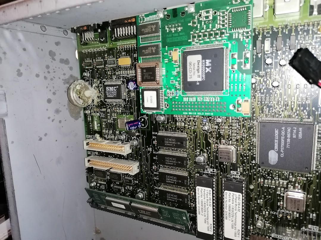
All I needed to do now is find out about the battery that I removed. Frustratingly there is almost no official information on the factory installed battery, and reading any information from my battery was out of the question due to the amount of corrosion present. I tried scraping some of it off, but it resulted in too much damage to the surface.
Whilst I was going about these tests, a member of one of the Acorn groups I am in on Facebook asked if I could check the connectivity between the SoC and the CMOS memory. Basically to confirm which pins were used for I2C from the SOC to this IC. His reason for this was quite interesting, he had a Bush IBX board, which is the guts of a smart TV box from a few years back, Apparently, these are cut down versions of the A7000/7000+. Modifying them to have the same CMOS functionality is part of the process of getting them to run RISC OS, its quite an interesting process and if I get my hands on one of those boards, it will definitely be something I will try out. I saw the end result of his efforts posted in the group recently and he had managed to get RISC OS 3.71 installed and running on it, which I think is pretty cool.
One of the things I wanted to address with the battery was could I use a battery of a different voltage, and could I use a battery of a different type? The battery that is normally installed on these machines is a Varta 280H or sometimes 300H NiMh 1.2 volt rechargeable cell with a capacity between 250 - 300 mAh. This is the component that was physically soldered to the board. Here it is still attached to the board:

I know that the CMOS RAM has an operating voltage of between 1 and 6 volts, so I know I can replace the damaged battery with another one that is between this range with a similar capacity. The next thing I wanted to find out is if I could swap from using a NiMh battery to a LiPo. After doing a lot of searching I discovered that the first Li-Ion batteries went on sale in 1991, which was only six years before this machine was made. After asking a few questions here and there it became apparent that no, I couldn't use a LiPo due to the fact the motherboard has no way to recharge the battery. I would need to provide the electronics for such a battery to do this safely and ensure it would work with the existing logic.
Naturally, I chose to use a NiMh instead.
As a complete stroke of luck, I happened to have the exact battery I needed for this to work. I was stunned to the point that I needed to take a moment and have an energy drink - so far I have embarked on a project and I just happen to have all the things I need to do what I need to do without ordering things in. Surely something is going to go wrong soon? The only difference being that the replacement battery was physically completely different, in the AA format, but thats OK.
Checking the battery over made sure that it put out something in the region of 1.2 volts and I set myself to learning why a NiMh is the easiest choice for this application. It turns out, according to Wikipedia, that NiMh batteries can trickle charge when connected to a power source over time. However, they cannot be used as they are being charged, and it takes time for them to charge up. My battery was almost fully charged, I think it came out of a solar powered light that I took the solar panel out of and just kept the battery next to my keyboard, so it is pretty new with almost no charge cycles. I also learned why having a battery with a higher voltage would have been a bad solution.
Because the battery installed on the motherboard would be trickle charging, it would take quite a long time for it to be available to the CMOS memory. If, for example, we had five of them connected together for 6 volts, it would take a lot longer for them to charge completely. Which means that the battery would not be available to the CMOS memory for a lot longer than it would take to charge a 1.2 volt battery.
This means that when you power off the machine, you lose your clock. You would need to reset the clock each time your turned on the machine and save that to CMOS until your battery pack had fully charged.
So keeping it broadly the same as the original part is the best course of action here. All I need to do is connect the AA battery to the relevant terminals and we are golden. But, before we do, lets address one of the design oversights with this board - the battery placement.
NiMh batteries like to leak, pretty much every AA battery I have come across in the last couple of weeks likes to leak, and when they do it can be a disaster. So connecting this battery directory to the board is a bad idea. So lets add a lead with a connector to the board, so we can move the battery away from it, reducing the ability to cause damage in the future.
We are going to solder a lead into the battery terminals that were exposed after removing the damaged part. The top two are marked as positive, red - you dont need to connect both of these to positive, one will do. But if you want you can fly a connection over between the two. Use the square pad to help you keep track of what you are doing. The single terminal on the opposite side is for negative, black. To keep things neat, you might want to poke the wires through the top of the board and solder from below.
Once soldered, we have a connector that takes us all the way to the edge of the motherboard:

Now that part is sorted, I need to take care of a battery holder or retainer. I had a go at making my own with some perf boards and some spare battery terminals that I was hoping to use on the Game Gear, but I wasnt happy with the result, so will keep that for prototyping. Instead, when looking through a box of potential stuff, I found some fairy lights that were powered by two AA batteries in a little enclosure. This was perfect for what I needed.


Removing the switch and single spring terminal gave me the basis to create a single AA battery holder. This also had a switch installed, which was also removed. The unused side of the battery enclosure was used to run a wire down to the double terminal. An opposing connector was added to the newly installed leads and I once again tested the output voltage to make sure it was OK. With the length of wire between the two new leads, I have quite a lot of flexibility when it comes to hiding this box in the case.

Now, what I really wanted to do was plug it straight in and see if it worked. But - this machine hadn't been turned on for a few years, and there had been damage to the board that I needed to clean up. Plus, I didn't know if having a completely wiped CMOS memory was a good thing at this point or what hitting it with 1.2 volts was going to do to it beyond the control of the motherboard. I also didn't just want to plug the PSU in and fire the mains up either without checking to make sure that the PSU was putting out the correct voltages etc - there was still a bit of testing to do, but as of right now I have almost achieved my goal...
But what I can do is install the battery holder in the chassis somewhere out of the way.

Using a single command strip, the battery case is held in its new spot, tucked away from anything it might hurt if a battery might go pop in the future. I think using a closed battery case will also help prevent any potential damage in the future.
Next up, we need to get started on testing the power supply and see if this is going to cause an explosion with my new battery...