Recently, I have been looking at the ATTiny85 for use in some tiny projects that I have been thinking about recently. This is an extremely small and versatile microcontroller that can be used in a number of different settings where space or size is a consideration.
You can typically see these used in the Digispark USB Development boards made by Digistump, it is a very distinctive board that you may have seen quite a lot. There are also a number of different ATTiny85 based development boards available on Amazon and eBay, the version I initially got for myself was from Amazon here.
One of the really cool things about the ATTiny85 is the fact that the microcontroller itself is so tiny, as of writing this article I have seen them in two packages, SOP-8 and a DIP-8. It is also possible to buy development boards that have a DIP-8 socket, so that you can provide your own ATTiny85. These are really useful, as it allows you to program your microcontroller before using it in your build.
 |
| example of an ATTiny85 development board with DIP-8 socket |
However, this comes with one drawback - the microcontrollers you buy at these prices from these locations will quite often come with no bootloader installed. So even if you follow all the instructions on how to use one of these with the Arduino IDE, for example, you will keep getting a message telling you that the "USB device connected is not working", or something very similar.
Annoyingly, even if you have a socketed development board, you still wont be able to install the bootloader, regardless of having it connected via USB.
So, you may have found this article because you are interested in flashing the bootloader on to an ATTiny85 - or you may be here because you have bought some cheap ATTiny85's from AliExpress and they are not recognised by Windows. This is what happened to me, and these are the steps I took in order to get them into a useable state. You may have also bricked your ATTiny85 and you need to reinstall the bootloader, these steps will also help you to get back into a working state.
To get this done, I used the following:
- A Windows 10 PC, 64 bit.
- An Arduino Uno R3
- A breadboard
- Some jumper wires
- A 100nF ceramic capacitor (code 104)
- a 10nf electrolytic capacitor
- A DIP-8 socketed ATTiny85 development board
- A DIP-8 ATTiny85
- The Arduino IDE
To get started, we are going to need to install the drivers for the ATTiny85 so that we can use it over a USB connection. This is going to be our primary means of communicating with this microntroller for the purposes of uploading sketches to it. Thankfully, we can make use of the drivers provided by Digistump, the latest release can be downloaded from their GitHub. Of the available downloads, we are specifically looking for the AVR release of the drivers, this is important for later on in the process.
There is also a second way of installing the drivers using Zadig, which is a little more complex. I dont really want to go into it too much here, but during this process, you will actually download the files you need to install the driver using Zadig instead.
Next, we need to get the Arduino IDE open and connected to our Uno. This is for a couple of reasons, firstly, we need to change the verbosity of the compile and upload process shown in the console window. To do this, open up the preferences by going to File, then Preferences.
Under the Settings tab, you will find something called "Show verbose output during", with two checkboxes for compilation and upload. Tick both and click OK to save.
Now, we need to make sure that the IDE is setup for the Uno. For most people who are used to doing this they can skip this step. For new users, go to Tools - Board: - Arduino AVR Board - Arduino Uno. Then set the port under Tools - Port. Quite often, the port you need to use is clearly marked as the one used by the Uno:
 |
| the Uno I used was clearly visible in the list of ports |
If yours doesnt show up like this then just disconnect your board and take a note of what ports are available. When you plug your board back in you will count one extra port. This is the port that your board will be using.
You can also check your available ports in the Device Manager, but this pretty much does the same as checking in the Arduino IDE. As you can see in my example, COM10 is clearly labelled as an Arduino Uno. However, depending on what type of Uno you have, you might see something different.

We now need to do the important bit, under Tools - Programmer, we need to select AVR ISP.
ISP, or In System Programming, is the method by which we are going to write the bootloader to our ATTiny85 further along.
Whilst we are in the Arduino IDE, we can configure it now for use with the ATTiny85 and development boards based on it.
Unfortunately, this controller/board is not available from the boards manager by default. So we need to provide a URL for an additional board manager. Thankfully, Digistump have provided just such a resource for us to use. To configure this, we need to add the URL from Digistump to our Arduino IDE preferences, these can be found in File - Preferences. Under the Settings tab, there is a text box where we can add our additional board manager URL, you can add as many of these types of URL as you like of you click the little button next to the text box. The URL we need to enter is:
http://digistump.com/package_digistump_index.json
Once entered, click on OK. Now head on over to the Boards Manager, in the search box type in Digistump. This will bring back all of the boards from Digistump that we just added via the URL, we are specifically looking for the Digistump AVR Boards option, this should be at the top of the list, but this is the one that we need to install.
Doing this will configure the Arduino IDE for use with our chip later on in this guide. It will also install all of the example sketches, which we will also want later on.
Once this is done, we need to verify that our connection to the board is working. We also need to verify that the board is working as well. To accomplish this, we can simply upload the Blink sketch. If everything works and Blink is executing, then the setup for this portion is complete.
We need to grab some important information from within the the write and compilation output in the console window. We are specifically looking for a reference to avrdude.exe and its configuration file. To find this, take a look down the log for Blink.hex - assuming that you uploaded the Blink sketch. Once you have found it, you will see the path for avrdude, for example the path for me was as follows:
Next up is the electronics, we need to set up some connections from our Uno to a breadboard according to this image:
 |
| note the electrolytic connected across reset and ground |
A couple of things to note here:
You can use crocodile clips to create the connection from the negative leg of the electrolytic capacitor to the ground rail. It makes things easier, as opposed to trying to stuff legs into single holes.
If you have the electrolytic capacitor installed as above, you wont be able to upload any sketches, it will cause the programmer to fail. This was an issue I ran into when trying to test my Uno was working, you can emulate this yourself, as far as I know it isnt damaging the Uno, it is just keeping it in a reset loop.
The ceramic capacitor is the 104, 100nf mentioned in the parts list above. It goes across the input voltage, however you may be able to get away with not using this, but it is something I did not try out myself as pretty much every diagram that explained this type of configuration used this capacitor.
And thats it, you dont need to do anything more than this to get writing to the chip. The final part we need to concentrate on is getting the bootloader to write to the microcontroller and creating the command needed to write it, along with some configuration.
The file needed to write to the chip can be found here, this is the GitHub repo for Micronucleus. Its a good idea to download the entire repo, or if you have Git installed, grab it on to your machine. We are specifically looking for a file called t85_default.hex which can be found in micronucleus/firmware/releases/
This repo also contains the relevant .cfg files you need to install the drivers via Zadig.
To get started on the command we need to execute to get the hex file written to our chip, I am going to use the PowerShell Integrated Script Environment. This is quite a good tool for putting together complex PowerShell commands by providing a scripting window as well as a PowerShell terminal in one place. This is part of the official PowerShell release from Microsoft, so should be available to you from the Start menu.
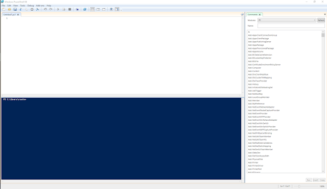
On first opening the ISE, you will see something like this:
 |
| from left to right - run, run selection, stop |
The bottom window is a regular PowerShell terminal. You will see the results of any script you execute here. You can also enter commands directly into the terminal and execute them if you want to.
Thats pretty much as I want to go into the ISE for now, I think it is a very useful tool to have and is awesome when you are creating PowerShell scripts. Now, we need to prepare a couple of things before we start building the command. Firstly, I am going to copy the t85_default.hex file I got from the Micronucleus Git repo above to C:\temp. This is just to make our command a little shorter.
The last bit of preparation is to navigate to the location where the avrdude executable is found - this is why we needed to download the AVR specific version of the Digispark ATTiny85 drivers earlier on. Again, this is to make the command a little shorter. To do this, we can use the PowerShell terminal in the ISE that we have open. We captured this location a little while earlier, so in the terminal we simply do this:

Listing the contents of this location will provide you with two folders. The bin folder holds the avrdude executable and the etc folder holds its configuration file. If you navigate to bin, you will be able to test that avrdude is available to you. Despite the fact that I already knew that avrdude was available for use by virtue of the fact that I had already used it via the Arduino IDE, I went ahead and executed it in the PowerShell terminal anyway and got the following:

If you are following along with this article and you can see this, then you are doing fine at this point. If you are getting an error message then close the ISE and open it again as an admin.
Now we know that avrdude is available to use via PowerShell, we can go ahead and start putting our command together. We are going to build that in the script window and I will go over it line by line trying to explain what is happening.
Because this command is going to be quite long, I am going to break it down into a couple of lines. You can do this in PowerShell to any command by putting a backtick "`" before starting a new line. You are going to see this at the end of almost every line we go through here.
The first line is simple, we are just going to execute avrdude:


On the third line, we are going to configure avrdude to write to our ATTiny85. The first flag I set is -v, this provides a verbose output, I always enable such a thing when I am doing something like this. I recommend it. Next is -P, this is where we provide the port number to use whilst writing to the chip. Choose the one that has been working for you in the Arduino IDE. However, please note that you wont be able to write anything to the chip if you already have an open connection to this serial port, and an open connection can be the serial monitor in the Arduino IDE itself. Next, we are going to set the programmer with the -c flag and set this to avrisp and the baud rate using the -b flag. Finally we set the product with the -p flag with attiny85:

The final thing we need to do with our command is configure the memory options we need to get everything written to the chip, and put it in a usable state. All memory operations are set with the -U flag, read/write, target and expected format.
Naturally, the aim of this process is to write a hex file to a microcontroller and the first memory operation on this line reflects this. However, I also discovered that we also need to write the fuses on the chip as well in order for us to be able to use it. I actually did a little bit of reading to find out some more on these fuses. They are not fuses in the sense that most of us would think of them, they are not components inside the chip that are designed to fail if something happens. Instead, these are actually bytes that store flags to enable and disable individual features of the chip itself.
So if you were like me, and you were wondering how you can write a fuse to a chip, what we are actually doing is writing something to a location in memory on the chip to configure its hardware.

After this, we have three separate write operations to memory. This is where the fuses are written, the memory type here is instead fuse. Instead of a path to a filename, we see instead a value in hex, and because of this the source format has been set to m.
This setting is for immediate mode, it means that avrdude will either provide input from the keyboard to be written to memory or from the command line. The hex value we see in the command is the location in memory that we need to write to. All the process wants to do is set that location to either on or off, writing to it sets it to on.
And thats it, everything we need to get our chip flashed is ready to go.
Make sure that your breadboard, chip are connected to the Uno and that you are connected via USB, then just press play from within the ISE and boom, the write process will get underway. That is as long as you can execute scripts on your system... If you have never done anything with PowerShell on your machine before, then the execution of unsigned scripts may be disabled and we need to change this in order to run our script. Basically, any scripts you create yourself will be unsigned unless you sign them yourself. Most of us will never need to sign a script, especially when we are working on things like this at home, so it is easier to change the execution policy.

We can do this by running set-executionpolicy remotesigned on the terminal, this will cause a window to pop up asking you to change the execution policy, click on the Yes button. This will allow you to run unsigned scripts locally, but signed scripts from the Internet.
Now when you run your script, it will execute, hopefully without errors. I cannot preempt all the problems and errors you may encounter. If you have been following along and have not encountered any errors so far, then I would suggest checking over the PowerShell script as this is likely to be where your issue could be. If anyone reading this does encounter a problem and they are not sure about what to do, I would gladly try and help out.
One issue you might encounter is not being connected to the correct COM port, or not being connected at all. The error you get for this is a little esoteric to say the least, however if you get this screen, then double check your connection:

Once the process is underway, you will get a lot of information about the current status of the chip written to the screen. You will see each memory operation that we specified in the PowerShell command get executed against our chip along with its status. The following snippet shows our hex file being written to the chip itself:

And that is it, our chip is now flashed and ready for use. We can try a quick test out here to prove it by uploading the Blink sketch to it. I did this by plugging the chip back in to my development board and opened the start sketch for the ATTiny85, you can get this from File - Examples - DigiSpark_Examples - Start.
One curious thing about the ATTiny85 is that it shouldn't be plugged in when you want to upload a sketch to it. Instead, you click the upload button and wait until the programmer asks you to connect the device, you will see this down in the console window. Once connected, you will see the sketch get uploaded and, fingers crossed, your development board will have a built in LED that starts blinking.
If you see this, you have just proven that the process you have undertaken flashes a blank ATTiny85 with its bootloader.
If your development board doesnt have a built in LED, instead bring bring one of the pins up high and low with a delay then bring it low. You can measure it with your meter against ground, you should see it go from zero to around 5 volts as the delay changes it status.
And there we have it, a method by which you can buy super cheap ATTiny85's from places like AliExpress and get them usable nice and fast. One thing I did to make my life easier was to build a very basic device that would allow me to do this even faster in the future. With a bit of stripboard and a couple of components, I built myself a little circuit that allows you to flash an ATTiny85 using the process above. It is nothing fancy at all, it just replicates what I had on the breadboard, but it means that all I need to do is wire it up and connect it to an Uno to get going, plus I was a little bored one day.
 |
| the chip in this diagram should be socketed, but there was no asset to represent this |
This is a very simplistic design, but it helps remove the annoyance of having to connect the electrolytic capacitor to the Uno itself.
IC1 represents our ATTiny85, the application I use to generate these images doesnt have anything for an 8 pin socket, so a bit of imagination is required here. Naturally, this is where our chip goes.
C2 removes the the electrolytic capacitor we had connected across ground and reset on the Uno itself. Now we just need to connect two cables back to the Uno. The bottom connection goes to reset on the Uno and the upper connection goes to ground on the Uno.
The connections for J1 are just the same as they were on the breadboard. Starting from the top we have:
- Vin
- Pin 13 on the Uno
- Pin 12 on the Uno
- Pin 11 on the Uno
This is what mine ended up looking like:

Just a point to make here about the build, those header sockets I am using there are the round type instead of the square type. They seem to be a lot easier to work with, especially when you are trying to squeeze jumper wires on to small builds. They are quite often cheaper as well:

Now that I am able to write the bootloader to my chips, I can get on with experimenting with them and hopefully using some in a couple of projects that I have in mind. If anyone has tried the process I have described above out, and encountered a problem that they cant get passed, I will gladly try to help out in the comments, or by even adding a new section or two to this article.
Also, it may be the case that Micronucleus is not the only bootlader that can be written to these chips. Recently, I have been reading about this really interesting project called V-USB...
Here are the links and resources I used to get this mini-project done:
Digistump GitHub:
https://github.com/digistump/DigistumpArduino/releases
Micronucleus GitHub:
https://github.com/micronucleus/micronucleus
Arduino IDE downloads:
https://www.arduino.cc/en/software
Zadig:
https://zadig.akeo.ie/
No comments:
Post a Comment