Showing posts with label arduino. Show all posts

Wednesday, 8 June 2022

Flashing The ATTiny85 Bootloader

 Recently, I have been looking at the ATTiny85 for use in some tiny projects that I have been thinking about recently. This is an extremely small and versatile microcontroller that can be used in a number of different settings where space or size is a consideration.

You can typically see these used in the Digispark USB Development boards made by Digistump, it is a very distinctive board that you may have seen quite a lot. There are also a number of different ATTiny85 based development boards available on Amazon and eBay, the version I initially got for myself was from Amazon here.

One of the really cool things about the ATTiny85 is the fact that the microcontroller itself is so tiny, as of writing this article I have seen them in two packages, SOP-8 and a DIP-8. It is also possible to buy development boards that have a DIP-8 socket, so that you can provide your own ATTiny85. These are really useful, as it allows you to program your microcontroller before using it in your build.

example of an ATTiny85 development board with DIP-8 socket


When you compare the price of the ATTiny85 itself against the price of a development board, you can see that the boards themselves, even without the microcontroller, cost a lot more. You can pick up 10 ATTiny85's from AliExpress for just under £5 - which is roughly the cost of one development board when you factor in how much shipping could be.


However, this comes with one drawback - the microcontrollers you buy at these prices from these locations will quite often come with no bootloader installed. So even if you follow all the instructions on how to use one of these with the Arduino IDE, for example, you will keep getting a message telling you that the "USB device connected is not working", or something very similar.

Annoyingly, even if you have a socketed development board, you still wont be able to install the bootloader, regardless of having it connected via USB.

So, you may have found this article because you are interested in flashing the bootloader on to an ATTiny85 - or you may be here because you have bought some cheap ATTiny85's from AliExpress and they are not recognised by Windows. This is what happened to me, and these are the steps I took in order to get them into a useable state. You may have also bricked your ATTiny85 and you need to reinstall the bootloader, these steps will also help you to get back into a working state.

To get this done, I used the following:

  • A Windows 10 PC, 64 bit.
  • An Arduino Uno R3
  • A breadboard
  • Some jumper wires
  • A 100nF ceramic capacitor (code 104)
  • a 10nf electrolytic capacitor
  • A DIP-8 socketed ATTiny85 development board
  • A DIP-8 ATTiny85
  • The Arduino IDE

To get started, we are going to need to install the drivers for the ATTiny85 so that we can use it over a USB connection. This is going to be our primary means of communicating with this microntroller for the purposes of uploading sketches to it. Thankfully, we can make use of the drivers provided by Digistump, the latest release can be downloaded from their GitHub. Of the available downloads, we are specifically looking for the AVR release of the drivers, this is important for later on in the process.

There is also a second way of installing the drivers using Zadig, which is a little more complex. I dont really want to go into it too much here, but during this process, you will actually download the files you need to install the driver using Zadig instead.

Next, we need to get the Arduino IDE open and connected to our Uno. This is for a couple of reasons, firstly, we need to change the verbosity of the compile and upload process shown in the console window. To do this, open up the preferences by going to File, then Preferences.

Under the Settings tab, you will find something called "Show verbose output during", with two checkboxes for compilation and upload. Tick both and click OK to save.

Now, we need to make sure that the IDE is setup for the Uno. For most people who are used to doing this they can skip this step. For new users, go to Tools - Board: - Arduino AVR Board - Arduino Uno. Then set the port under Tools - Port. Quite often, the port you need to use is clearly marked as the one used by the Uno:

the Uno I used was clearly visible in the list of ports

If yours doesnt show up like this then just disconnect your board and take a note of what ports are available. When you plug your board back in you will count one extra port. This is the port that your board will be using.

You can also check your available ports in the Device Manager, but this pretty much does the same as checking in the Arduino IDE. As you can see in my example, COM10 is clearly labelled as an Arduino Uno. However, depending on what type of Uno you have, you might see something different.


We now need to do the important bit, under Tools - Programmer, we need to select AVR ISP. 

ISP, or In System Programming, is the method by which we are going to write the bootloader to our ATTiny85 further along.

Whilst we are in the Arduino IDE, we can configure it now for use with the ATTiny85 and development boards based on it. 

Unfortunately, this controller/board is not available from the boards manager by default. So we need to provide a URL for an additional board manager. Thankfully, Digistump have provided just such a resource for us to use. To configure this, we need to add the URL from Digistump to our Arduino IDE preferences, these can be found in File - Preferences. Under the Settings tab, there is a text box where we can add our additional board manager URL, you can add as many of these types of URL as you like of you click the little button next to the text box. The URL we need to enter is:

http://digistump.com/package_digistump_index.json

Once entered, click on OK. Now head on over to the Boards Manager, in the search box type in Digistump. This will bring back all of the boards from Digistump that we just added via the URL, we are specifically looking for the Digistump AVR Boards option, this should be at the top of the list, but this is the one that we need to install.

Doing this will configure the Arduino IDE for use with our chip later on in this guide. It will also install all of the example sketches, which we will also want later on.

Once this is done, we need to verify that our connection to the board is working. We also need to verify that the board is working as well. To accomplish this, we can simply upload the Blink sketch. If everything works and Blink is executing, then the setup for this portion is complete.

We need to grab some important information from within the the write and compilation output in the console window. We are specifically looking for a reference to avrdude.exe and its configuration file. To find this, take a look down the log for Blink.hex - assuming that you uploaded the Blink sketch. Once you have found it, you will see the path for avrdude, for example the path for me was as follows:

C:\Users\rsain\AppData\Local\Arduino15\packages\arduino\tools\avrdude\6.3.0-arduino17

Next up is the electronics, we need to set up some connections from our Uno to a breadboard according to this image:

note the electrolytic connected across reset and ground

A couple of things to note here:

You can use crocodile clips to create the connection from the negative leg of the electrolytic capacitor to the ground rail. It makes things easier, as opposed to trying to stuff legs into single holes.

If you have the electrolytic capacitor installed as above, you wont be able to upload any sketches, it will cause the programmer to fail. This was an issue I ran into when trying to test my Uno was working, you can emulate this yourself, as far as I know it isnt damaging the Uno, it is just keeping it in a reset loop.

The ceramic capacitor is the 104, 100nf mentioned in the parts list above. It goes across the input voltage, however you may be able to get away with not using this, but it is something I did not try out myself as pretty much every diagram that explained this type of configuration used this capacitor.

And thats it, you dont need to do anything more than this to get writing to the chip. The final part we need to concentrate on is getting the bootloader to write to the microcontroller and creating the command needed to write it, along with some configuration.

The file needed to write to the chip can be found here, this is the GitHub repo for Micronucleus. Its a good idea to download the entire repo, or if you have Git installed, grab it on to your machine. We are specifically looking for a file called  t85_default.hex which can be found in micronucleus/firmware/releases/

This repo also contains the relevant .cfg files you need to install the drivers via Zadig.

To get started on the command we need to execute to get the hex file written to our chip, I am going to use the PowerShell Integrated Script Environment. This is quite a good tool for putting together complex PowerShell commands by providing a scripting window as well as a PowerShell terminal in one place. This is part of the official PowerShell release from Microsoft, so should be available to you from the Start menu.

On first opening the ISE, you will see something like this:
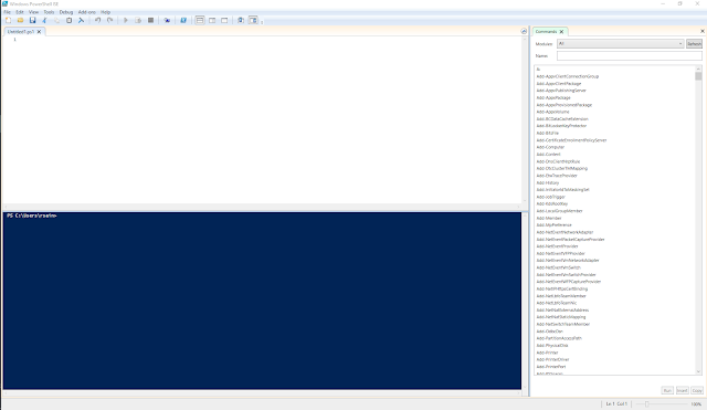


To give a very brief explanation of how the ISE works, the top section is the script window. Here you can write and execute PowerShell scripts using the standard play and stop buttons that you will find in most IDE's. One cool thing about the ISE is that you can select a portion of your script and choose to just run that instead of everything at once - this can be very useful when trying to find breaks.

from left to right - run, run selection, stop

The bottom window is a regular PowerShell terminal. You will see the results of any script you execute here. You can also enter commands directly into the terminal and execute them if you want to.

Thats pretty much as I want to go into the ISE for now, I think it is a very useful tool to have and is awesome when you are creating PowerShell scripts. Now, we need to prepare a couple of things before we start building the command. Firstly, I am going to copy the t85_default.hex file I got from the Micronucleus Git repo above to C:\temp. This is just to make our command a little shorter.

The last bit of preparation is to navigate to the location where the avrdude executable is found - this is why we needed to download the AVR specific version of the Digispark ATTiny85 drivers earlier on. Again, this is to make the command a little shorter. To do this, we can use the PowerShell terminal in the ISE that we have open. We captured this location a little while earlier, so in the terminal we simply do this: 


Listing the contents of this location will provide you with two folders. The bin folder holds the avrdude executable and the etc folder holds its configuration file. If you navigate to bin, you will be able to test that avrdude is available to you. Despite the fact that I already knew that avrdude was available for use by virtue of the fact that I had already used it via the Arduino IDE, I went ahead and executed it in the PowerShell terminal anyway and got the following:


If you are following along with this article and you can see this, then you are doing fine at this point. If you are getting an error message then close the ISE and open it again as an admin.

Now we know that avrdude is available to use via PowerShell, we can go ahead and start putting our command together. We are going to build that in the script window and I will go over it line by line trying to explain what is happening.

Because this command is going to be quite long, I am going to break it down into a couple of lines. You can do this in PowerShell to any command by putting a backtick "`" before starting a new line. You are going to see this at the end of almost every line we go through here.

The first line is simple, we are just going to execute avrdude:

For the next line, we will use the -C flag. This allows us to provide the current execution of avrdude the location of an external configuration file that we want to use. This is an important step - we need to use the config file that has been set up by the Arduino IDE because we know that this one works. We dont need to create a new one.


On the third line, we are going to configure avrdude to write to our ATTiny85. The first flag I set is -v, this provides a verbose output, I always enable such a thing when I am doing something like this. I recommend it. Next is -P, this is where we provide the port number to use whilst writing to the chip. Choose the one that has been working for you in the Arduino IDE. However, please note that you wont be able to write anything to the chip if you already have an open connection to this serial port, and an open connection can be the serial monitor in the Arduino IDE itself. Next, we are going to set the programmer with the -c flag and set this to avrisp and the baud rate using the -b flag. Finally we set the product with the -p flag with attiny85:


The final thing we need to do with our command is configure the memory options we need to get everything written to the chip, and put it in a usable state. All memory operations are set with the -U flag, read/write, target and expected format. 

Naturally, the aim of this process is to write a hex file to a microcontroller and the first memory operation on this line reflects this. However, I also discovered that we also need to write the fuses on the chip as well in order for us to be able to use it. I actually did a little bit of reading to find out some more on these fuses. They are not fuses in the sense that most of us would think of them, they are not components inside the chip that are designed to fail if something happens. Instead, these are actually bytes that store flags to enable and disable individual features of the chip itself.

So if you were like me, and you were wondering how you can write a fuse to a chip, what we are actually doing is writing something to a location in memory on the chip to configure its hardware.


The first section of line 4 specifies that the type of memory we want to use is flash, w indicates that we wish to write to this memory. The full path to the hex file we downloaded earlier is provided here, the i at the end indicates that this is in the intel hex format.

After this, we have three separate write operations to memory. This is where the fuses are written, the memory type here is instead fuse. Instead of a path to a filename, we see instead a value in hex, and because of this the source format has been set to m.

This setting is for immediate mode, it means that avrdude will either provide input from the keyboard to be written to memory or from the command line. The hex value we see in the command is the location in memory that we need to write to. All the process wants to do is set that location to either on or off, writing to it sets it to on.

And thats it, everything we need to get our chip flashed is ready to go. 

Make sure that your breadboard, chip are connected to the Uno and that you are connected via USB, then just press play from within the ISE and boom, the write process will get underway. That is as long as you can execute scripts on your system... If you have never done anything with PowerShell on your machine before, then the execution of unsigned scripts may be disabled and we need to change this in order to run our script. Basically, any scripts you create yourself will be unsigned unless you sign them yourself. Most of us will never need to sign a script, especially when we are working on things like this at home, so it is easier to change the execution policy.


We can do this by running set-executionpolicy remotesigned on the terminal, this will cause a window to pop up asking you to change the execution policy, click on the Yes button. This will allow you to run unsigned scripts locally, but signed scripts from the Internet.

Now when you run your script, it will execute, hopefully without errors. I cannot preempt all the problems and errors you may encounter. If you have been following along and have not encountered any errors so far, then I would suggest checking over the PowerShell script as this is likely to be where your issue could be. If anyone reading this does encounter a problem and they are not sure about what to do, I would gladly try and help out.

One issue you might encounter is not being connected to the correct COM port, or not being connected at all. The error you get for this is a little esoteric to say the least, however if you get this screen, then double check your connection:


Once the process is underway, you will get a lot of information about the current status of the chip written to the screen. You will see each memory operation that we specified in the PowerShell command get executed against our chip along with its status. The following snippet shows our hex file being written to the chip itself:


And that is it, our chip is now flashed and ready for use. We can try a quick test out here to prove it by uploading the Blink sketch to it. I did this by plugging the chip back in to my development board and opened the start sketch for the ATTiny85, you can get this from File - Examples - DigiSpark_Examples - Start. 

One curious thing about the ATTiny85 is that it shouldn't be plugged in when you want to upload a sketch to it. Instead, you click the upload button and wait until the programmer asks you to connect the device, you will see this down in the console window. Once connected, you will see the sketch get uploaded and, fingers crossed, your development board will have a built in LED that starts blinking.

If you see this, you have just proven that the process you have undertaken flashes a blank ATTiny85 with its bootloader.

If your development board doesnt have a built in LED, instead bring bring one of the pins up high and low with a delay then bring it low. You can measure it with your meter against ground, you should see it go from zero to around 5 volts as the delay changes it status.

And there we have it, a method by which you can buy super cheap ATTiny85's from places like AliExpress and get them usable nice and fast. One thing I did to make my life easier was to build a very basic device that would allow me to do this even faster in the future. With a bit of stripboard and a couple of components, I built myself a little circuit that allows you to flash an ATTiny85 using the process above. It is nothing fancy at all, it just replicates what I had on the breadboard, but it means that all I need to do is wire it up and connect it to an Uno to get going, plus I was a little bored one day.

the chip in this diagram should be socketed, but there was no asset to represent this


This is a very simplistic design, but it helps remove the annoyance of having to connect the electrolytic capacitor to the Uno itself.

IC1 represents our ATTiny85, the application I use to generate these images doesnt have anything for an 8 pin socket, so a bit of imagination is required here. Naturally, this is where our chip goes.

C2 removes the the electrolytic capacitor we had connected across ground and reset on the Uno itself. Now we just need to connect two cables back to the Uno. The bottom connection goes to reset on the Uno and the upper connection goes to ground on the Uno.

The connections for J1 are just the same as they were on the breadboard. Starting from the top we have:

  • Vin
  • Pin 13 on the Uno
  • Pin 12 on the Uno
  • Pin 11 on the Uno
There is only one connection from J2, the top connection is connected to pin 10 on the Uno.

This allows me to have something that is purely dedicated to flashing the bootloader on to an ATTiny85 whenever I need to. Naturally, I could have made the connections a little more intuitive, and there is a way you could use the same board for uploading sketches to the chip - but I want this to do one thing and one thing only, and that is to flash the bootloader. I also want it to be a process I have to think about, so that I dont wipe out a bootloader on a chip I have a working project on, it needs to be an intentional move to stop me from messing up.

If you go ahead and create something like this for yourself, make sure that you cut the tracks under the socket for IC1. This is stripboard, so everything is connected on one axis. Whilst this is very useful, you will need to cut those tracks for the build to work.

This is what mine ended up looking like:


Just a point to make here about the build, those header sockets I am using there are the round type instead of the square type. They seem to be a lot easier to work with, especially when you are trying to squeeze jumper wires on to small builds. They are quite often cheaper as well:


Now that I am able to write the bootloader to my chips, I can get on with experimenting with them and hopefully using some in a couple of projects that I have in mind. If anyone has tried the process I have described above out, and encountered a problem that they cant get passed, I will gladly try to help out in the comments, or by even adding a new section or two to this article.

Also, it may be the case that Micronucleus is not the only bootlader that can be written to these chips. Recently, I have been reading about this really interesting project called V-USB...

Here are the links and resources I used to get this mini-project done:

Digistump GitHub:

https://github.com/digistump/DigistumpArduino/releases

Micronucleus GitHub:

https://github.com/micronucleus/micronucleus

Arduino IDE downloads:

https://www.arduino.cc/en/software

Zadig:

https://zadig.akeo.ie/


Saturday, 5 September 2020

Serial Communications with Arduino Part 2 - Software Serial Ports

 Last recently, I put up a short post on how we can use Arduino to read data from a device. Cunningly, I made the process so simple (mainly for myself) that I neglected to actually use an Arduino.

So, in this post I will remedy that by providing an example on how to read data from a device using serial communication at the start, then move on to writing to the serial port.

In the last post, I gave an example of how you can connect a USB to TTL adapter to a device and read its data. This time round, we are going to use the UNO R3 to act as our USB to serial adapter. To do this, we are going to be using the following

  • 1x    breadboard
  • 1x    Arduino UNO R3 
  • 1x Neo-6M/GY-GPS6MV2 GPS Module
  • 1x CH340 USB to TTL adapter
  • Jumper wires

The proposition is quite simple; we want to send the output of the GPS module to the board over a serial port. Unfortunately, I have not found a way to simply connect it to the TX/RX pins on the board itself and have it output data. So, to accomplish this we need to create a second serial port to handle the incoming stream of information from the GPS module itself and we need to create that port in software.

To do this, we are going to have to use the Software Serial Library.:

1:  #include "SoftwareSerial.h"  
2:  SoftwareSerial ss(8, 9);  
The first line references the library we need to use in this program. If you get an error when compiling this code, you might want to check that you have this library installed from within the Library Manager.

The second line is simply us creating a new software serial port called "ss", the numbers following represent the RX and TX pins on the board.

Next, we have to set up our ports, this should be familiar to anyone who has been using the Serial Monitor from within the Arduino IDE: 
1:  void setup() {  
2:   // put your setup code here, to run once:  
3:   Serial.begin(9600);  
4:   ss.begin(9600);  
5:  }  

Here we can see that on line 3 the hardware serial port is started with a baud rate of 9600 - this is the speed at which the port is reading/writing at. Line 4 is almost exactly the same, however this is the software serial port that is being started this time, note that we are also starting it at the same baud rate.

From reading up on using this library, it seemed that 9600 was the highest baud rate to go for and still have a stable connection. The GPS module can work up to 115200 baud, however when I configured the serial ports to use this speed, nothing happened.

Next up, we have the main executing of the code itself. We read the data leaving the GPS module on its TX port on to the boards hardware RX port and vice versa: 
1:  void loop() {  
2:   // put your main code here, to run repeatedly:  
3:   if (ss.available())  
4:    Serial.write(ss.read());  
5:   if (Serial.available())  
6:    ss.write(Serial.read());  
7:  }  

Line 3 checks to see if the software serial port is available, if it is then the hardware serial port then writes whatever the software serial port is reading on line 4.

Line 5 does the opposite, if the hardware serial port is available the software serial port writes whatever the hardware serial port is reading - which happens to always be whatever the software serial port is reading due to the structure that we have created.

Think of the above as an exchange - the hardware serial port is empty until it reads the incoming message from the software serial port. Once it has that, then both ports will have the same message.

Make sure you have your serial monitor running when you upload the code, you should see something like this:


The full listing for the code will be at the bottom of this post.

At the start of this article I mentioned that I used a CH340 USB to TTL adapter for debugging. This is because I had a fairly hard time getting the software serial port actually doing what I wanted it to do, quite a few of the articles I had read on the subject provided examples that simply did not work so I began to think my GPS module had become damaged.

So, to verify that the GPS module was working whilst the board was running the code, I connected it in series with the wires going from the GPS module to the board.

This let me run putty to make sure that I was getting something from the GPS module itself and make sure there was an incoming message for the board to do something with. It was actually quite helpful to do this while figuring out my problem. 

The setup, minus the USB to TTL adapter, looks like this:


If you are trying this out for yourself, then hopefully you are seeing a nice barrage of NMEA sentences scrolling across your serial monitor.

However, if you are seeing nothing, then try swapping your RX/TX pins on the board itself. You might have gotten them mixed up - I certainly did a couple of times.

SoftwareSerial is not the only library available that can do the same thing. Another, very popular library you can install is AltSoftSerial. Syntactically, it is almost identical to SoftwareSerial and supports a wide arrange of MCU's and development boards. You can also use a mixture of different libraries to give yourself multiple serial ports to work with, should you need to, for example if you had a number of devices that provided data in the same way as the GPS module you will need to have more than one serial port configured to a set of pins. That way you will have an uninterrupted flow of data from each device on its own serial port.

So what does all of this mean? Well essentially it is just a description of how you can easily set up a couple of serial ports to share data. But in this specific context, where could we take the build next? We are using a GPS module and we can see the NMEA sentences that it is receiving. We also know that each sentence begins with a $, so we could easily read the sentences into an array or object in order to process them further.

From looking at the output, we can see that there are six distinct types of sentence being received, or at least the module is trying to populate the contents of six sentences with data from the GPS constellation, with that knowledge we might be able to do something useful with that data...

The full code listing for used for this article is as follows: 

1:  #include "SoftwareSerial.h"  
2:    
3:  SoftwareSerial ss(8, 9);  
4:    
5:  void setup() {  
6:   // put your setup code here, to run once:  
7:   Serial.begin(9600);  
8:   ss.begin(9600);  
9:  }  
10:    
11:  void loop() {  
12:   // put your main code here, to run repeatedly:  
13:   if (ss.available())  
14:    Serial.write(ss.read());  
15:   if (Serial.available())  
16:    ss.write(Serial.read());  
17:  }  


Sunday, 5 July 2020

Using Transistors As a Switch with Arduino

 Recently, I have had reason to look into switches and how they can work with Arduino, and other popular MCU's.

This is part of a larger piece of investigation that is looking into buttons, sliders, potentiometers, switches etc as inputs whilst I think about how to make my own keyboard.

Of course, everyone has heard of a transistor. We all have some form of awareness as to how important they are with regards to the evolution of technology and computing. But what is a transistor really? Anyone with a background, or an interest in computing will probably tell you that they are used to calculate things on a CPU, and they are correct - but this isnt what transistors are limited to.

I am not going to go into the science of transistors here or how they work on a microelectronic level, there are plenty of other blogs and articles who have done a much better job than I could ever do. What I am aiming to do here is to give a quick guide on how to pretty much use a transistor as a switch, how to connect one up and how to control one in the code.

Transistors basically can do two things; they act as switches and they can help amplify signals. And they do this by controlling the current flowing through them. However today, I am only going to be talking about how they can be used as a switch in this article. You may be asking why would you want to use a transistor as a switch? There are no physical controls, so you would need to programmatically control it - and that's the beauty of using a transistor as a switch.

One really good example of how this can be used could be this - you have a light somewhere that you want to turn on when it gets dark. You build a circuit with a lamp, and a light sensor. When the state of the light sensor reaches a certain point, you then want the lamp to light up. So you can use a transistor to act as the switch to do this.

Naturally, all of this would require an MCU of some type as well as some code, but it really is a nice little example of a potential application.

One of the neat features of using a transistor as a switch is, depending on your transistor, that you may be able to switch on a circuit of a much higher voltage. This is because a lot of transistors are capable of handling a lot more voltage because of their amplification abilities.

Transistors typically come with three pins, which are cryptically called:

  • Collector: This is normally the current you are trying to control.
  • Base: This is normally the current you use for the switch. It controls the bias on the transistor.
  • Emitter: This normally goes to ground.
For the examples below, I will be using the following components:

  • 2x 1 kohm resistors
  • 1x red LED
  • 1x PN2222A transistor
  • 1x Pro-Micro/Arduino Nano MCU

Here is an example diagram to help visualise this:


On this breadboard we have a transistor acting as a switch to control the LED. When 5 volts is applied to the power rail, the LED will light up, if I remove the transistor from the circuit then apply power, the LED would not light up.

Why is this? Well, to explain this, lets look at the names of the pins in relation to the connections in the diagram. 

Starting from left to right, we have the collector first on pin 1. This has the LED connected to it, with a 1K resistor running to 5 volts. This part of the circuit represents the current we are trying to control.

The middle pin, pin 2 - we have the base. This is the switch itself, when enough current is passing through it, the switch is closed. When there is insufficient, or zero current flowing through it, the switch is open. This controls the flow of current through the collector - this means when the switch is closed, current flows through the collector and the LED lights.

On the right, we have the third pin, which is tied to ground.

If you construct this circuit, there are two ways to test it. Firstly, remove the transistor from the circuit and apply power - the LED should be off. If it is on, then you are passing power to the LED without the transistor controlling it.

Second, disconnect power from the base, this should turn off the LED. If it doesnt, then again - you are probably passing power to the LED outside of the control of the LED.

Now, the above shows a transistor controlling current to an LED using 5 volts, but remember when I said they can also be used to control the current in circuits that require a higher voltage? We can create an example of this as well, but this time using 3.3 volts to control the transistor whilst still using 5 volts to light the LED:

All that has changed in this example is that we are now applying 3.3 volts to the lower power rail as well as 5 volts to the upper power rail. When the power is connected, the LED will light up.

One point to note here is that using a transistor in this setting is rather pointless. All this circuit does is provide power to an LED. This can lead to some confusion  when building such a circuit for testing or educational purposes.

So how about we create the classic "blink", but this time using our transistor? To do this, we are going to need to use a micro controller, for this example I am going to use a Pro-Micro/Arduino Nano using 5 volts. This means we can keep our initial breadboard design the same, more or less.

All we need to do is alter the way the transistor is biased. Instead of simply being powered directly from the power rail, we are going to connect it to a GPIO pin:


This is the same circuit as the one I initially built. It is orientated differently to accommodate its one difference, and that difference is how we are controlling the base on the transistor.

Previously, we were simply providing it with current, which caused the LED to be illuminated for as long as power was available. However in this example, we have connected the base to pin 2 on the Nano. Unless you make it happen, pin 2 will not be high, which means if you create this circuit and power it, the LED will not light up.

So, on to the the classic "blink", to achieve this we need to write a couple of lines of code, the whole thing is this:


 1
 2
 3
 4
 5
 6
 7
 8
 9
10
11
12
13
void setup() {
  // put your setup code here, to run once:
  pinMode(2, OUTPUT);

}

void loop() {
  // put your main code here, to run repeatedly:
  digitalWrite(2, HIGH);
  delay(1000);
  digitalWrite(2, LOW);
  delay(1000);
}


The setup for this is simple, we just need to define the pin we are going to use to control the base. In the diagram we have it connected to pin 2, so that is what we define here. We need this to be used for output, as we will be sending a signal to the transistor.

The main body of the program should be familiar to anyone who has tried out the blink sketch that is used to test out various developer boards. We simply take pin 2 high for a couple of seconds before sending it low for the same amount of time.

This basically opens and closes the transistor as if it were a switch, if you try this out for yourselves, you will see the LED blinking on and off every couple of seconds.

Now, lets get in to some specific points that are worth mentioning:

Using resistors is essential. Not putting a resistor across a transistor in the way I have shown above can often cause your transistor to melt, it certainly did for me unless the ones I had were also defective. It is important to note that the resistors you use should be of the appropriate resistance for your load - it wont always be 1 kOhm.

The examples above use an Arduino Nano, but everything here is also compatible with the cheaper Pro-Micro developer board. The only difference between the two boards is that one provides a 3.3 volt rail and the other doesn't.

Using a GPIO pin to control the biasing of a transistor is the win here. The state of the transistor can be governed by the state of a separate sensor(s), the result of a programmatical state or pretty much anything that is capable of changing the state of that pin.

For me, it was fun but a little frustrating learning about how transistors work. Writing this blog entry has been part of my learning process and perhaps someone will find it useful in the future themselves :)

Friday, 3 July 2020

Creating a 5 Volt DC Power Supply

 Just over a year ago I bought myself a robotics experiment kit from Amazon to play with during some downtime.

Naturally, a lot of us have had a lot of spare time (sort of) on our hands lately. So this gave me the opportunity to get this kit out and start playing around.

On opening it up, I discovered that it wasn't just a robotics kit, it was actually an Arduino based experiments kit. For those of you who don't know, Arduino itself is an open source hardware electronics platform. The open source bit is how their kit works, naturally you need to buy the hardware itself - or if you are skilled enough, you can make it yourself from the schematics and tools Arduino provides.

You can get more information about Arduino gear on their site as well as browse their store. I need to point out that I am in no way affiliated with Arduino, or get anything for writing about them.

In fact, it is often cheaper to browse eBay for Arduino clone boards than it is to buy the official ones, but that is a story for another day.

Now, back to the point. Once I had finished all the experiments described in the kit, I decided to try my hand at building some actual devices for myself. Of course at this point, I wasn't quite sure what to build, but I knew one thing, what ever it is I decided to build, it would need to be powered in some way.

One of the interesting things I discovered working with these electronics is that pretty much everything, including consumer electronics, runs from a DC power source. This means when you are building something, powering it from a wall outlet or a battery is usually interchangeable. The work you have to put in is how you condition this power source (for want of a better phrase).

To do this, we need to use a voltage regulator. A voltage regulator is an electronics component that is designed to control the forward flow of power from a power source, like a USB lead or a battery, onwards to your circuit. Wikipedia has a very good article on the subject here if you are a newbie like me and want to learn some more. In their simplest form, they will have three pins, voltage in, voltage out and a ground pin.

When building my own power supply, I wanted to use the same voltage regulator that came with the micro controller that came in my experiments kit - this was a Mega 2650. In order to find out where the voltage regulator might be (don't forget, my knowledge of electronics is very basic at this point) I referred to the boards schematics. I don't really understand how to read these very well at this point, but was easily able to see where the power for the board comes in, you can take a look at them here the power input is in the top left hand corner. After googling the name of all the components, I found what I was looking for, the MC33269D 5. This little guy is intended to take a DC current through the barrel connector and drop it down to 5 volts DC for the board to operate. Most people will never use this method though, as most of us will be powering the device via USB, which will also give you 5 volts DC.

However, when I went to look for this component on my board, it was missing. Mine seems to come from a company called Elegoo, which are a good place to get hobby electronics kit, so wasn't a cheap clone. In its place, we have an AMS1117-5, after a quick search I discovered that this is also a 5 volt DC regulator, I also found the same component on a few other boards I have. So it made sense to build my power supply around this component, it is cheap and readily available from places like eBay, Amazon as well as Mouser etc.

Another new thing for this bit of work that I am using is a tool to help me plan and design my build. Previously, if I was working on a largish experiment on the breadboard the most work I would put in to designing something was maybe a scribble in a notepad. That's fine when you can change any wire or component when ever you like, but when you are soldering things down you want to be 100% sure that you are putting the right thing in the right place and its orientated in the right way. Otherwise you can ruin a whole build and you may need to start from scratch... This is the voice of experience talking.

When looking for examples of Arduino circuits, you will often run in to these wonderful little images that simulate the layout on a breadboard. I wanted to use this in my posts going forwards, so I tracked down the tool used to make them. Again, I am not affiliated with this company, and I dont get anything from them and you need to pay for this tool, but it is available from Fritzing. In my humble opinion, the license is very cheap for what you get and for those who are inclined, you can download the source for free and compile it yourself. However I am not going to go into that here. This isnt going to be a tutorial on how to use Fritzing either, its a really easy to use package and is essentially drag and drop. As a tool for helping me with my little builds, it has been extremely helpful and has enabled me to learn more about what it is I am doing.

So, lets get started by creating a new design and putting a voltage regulator on it. Fritzing doesnt have a dedicated symbol for the AMS1117, so a search for this will give you pretty much nothing you can use. However if you search for 1117, you will get something called a "V_REG_LD1117VXX". This will do for the purposes of design, layout and even construction, depending on how you build this. The LD1117 precedes the AMS117, so lets get this out on to the board:

Before we go any further, we need to take a step back and address reality here for a second. If you found this article after looking for ways to create a 5 volt DC power supply for real then we need to talk about the package the AMS1117 family comes in. For the sake of illustration, I am using a TO-220 package to represent the voltage regulator. In reality, the AMS1117 family are all in the SOT-23 package (to the best of my knowledge). This is a lot smaller than the one pictured here and while it is possible to solder one of these by hand to some 2.54mm pitch protoboard, you are not going to be able to use one on a breadboard easily.

However, you can get adapters that will allow you to mount pins to a SOT-23 package, these are basically SOT-23 to DIP adapter plates. You can get them from all the major stockists online, but I found the cheapest place to get them so far is eBay, an example of some can be found here. This is what an AMS1117-5 looks like when it has been installed to one of these adapters, you can see how this will make things easier:


AMS117-5 next to SOT 23 to DIP adapter


You can use some flux to hold the regulator in place for soldering.


Try to solder one of the outer pins first. This will make the rest easier.


To finish off, you just need to add some 2.54mm pitch header pins and you are done. An easy way to solder components like this is to use a breadboard for support:

Some extra headers are laid flat at the other end for support.


Get some flux on and get one of the pins soldered into place, you can make sure it is square here before continuing to solder the remaining pins. Don't worry about getting it done perfectly at this point, we don't want the plastic on the headers to melt.

If you need to, go back over the joints to make sure they are even and then you are done. You should end up with something like this:


If this is the first time you have done something like this - well done, you just made your first very own component! You can now go on and use this in your own breadboarding as a 5v DC voltage regulator!

Now, back to the design. I need to make a few changes here to the symbols properties in order to make it more visually relevant to the build. The changes I make are as follows:


Now we need to push some power into this, you could assume that it is coming from a 9 volt battery, such as a PP9. Technically, you could connect the plus and minus pins from the battery directly to the battery and it could output a 5 volt supply, however that's not really how it works. We need to get a few more components in there before we can actually start using this. To start with, we want to make sure that power cant come back through the circuit and damage the battery - or whatever power source you are using. So we need to stick a diode between the battery's cathode, positive line, and the forward flow to the voltage regulator. A diode is essentially a one way gate, a current can flow through it one way, but not the other. This makes it ideal for protecting your power source.

With this done, I need to add in some capacitors. If you take a look at the NCP1117-5 datasheet, which is also very similar to the AMS117 family, you can see a breakdown of the output capacitance vs the  equivalent series resistance (ESR). Output capacitance here refers to the capacitors we need to put in to the circuit as power leaves the voltage regulator and from looking at the graphs on page six of the datasheet, we can see that a 100uf electrolytic capacitor flowing to a 100nf ceramic capacitor will provide what we need. This will help smooth out the flow of power as it moves through the circuit - I am also going to do the same thing as power goes in to the voltage regulator as well for the same reason.

Next up is to simply add something in to indicate that there is power running through the circuit, this can easily be done with a 1k resistor and a red LED. The completed breadboard could look something like this:


Naturally, this probably isnt the best way to illustrate the layout. I am still getting used to the tool, but it certainly makes you think about what you are doing before you do it and why you are doing it. For the above to work, you simply need to provide a DC power source greater than 5 volts on one end. The LED will light up to show the circuit is working, to test it you can get your meter out and measure the incoming supply before it hits the voltage regulator to see what is being fed into it. The design above ends in a screw terminal providing both positive and negative, you can measure here as well to see that you get a steady 5 volts, or there about. 

Don't worry if it is slightly under or over, what we need to check is the stability of the voltage. If you are seriously over or under 5 volts, then it is highly likely your regulator is either broken, or an incredibly poor quality copy.

Now, if you want to, you can go ahead and build this on a piece of protoboard, but - before you do, why not model that in Fritzing as well? You can actually design on protoboards of different types in this application as well as use a breadboard, so if you are like me, you can design what you want on screen first before you commit it to the board. As long as it has been designed correctly - which you test out on the breadboard first - all you need to do is make a physical copy. Its also good for documenting what you have done if you commit your work to source control.

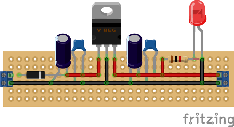
The protoboard version of this build could look like this:


The board I ended up making looked like this:


When designing the protoboard version in software, I specifically used the same size and layout that I have for in my collection of physical protoboards. My soldering isnt great, neither is my use of space, layout etc. Also, please note that I didn't install the LED, despite putting the resistor for it in place.

However, this works. I have feed it up to 10 volts so far and it has maintained a steady 5v DC with very little heat. This is a relatively small build, if you look at the photo this is being propped up by a pen, the whole board is about half the size of the pen, so it gives you some idea of scale.

But, it wont stop here. There are a couple of improvements that I can think of already, such as adding a switch. It would be good to see how small I can get this as well.

One interesting thing to note about this design is that you can swap out the voltage regulator for the 3.3 volt version and it will still work. You don't need to change the capacitors. I guess you could probably make a switched power supply that could let you select either 5 or 3.3 volts.