Monday, 8 August 2022

Repairing the Sega Game Gear - Part 1

The other day I was talking to one of my friends about a drop in screen replacement kit I have for the Atari Lynx 2, something that I hope to cover in a future post, and mentioned how amazing that handheld was. I got around to showing some of the contemporary handhelds that were around at the time, including the Sega Game gear.

Sega were my all time favourite console makers, and when they backed out of the hardware business I almost cried. I have so many good childhood memories playing the Master System and Megadrive. I never had the chance to own a Game Gear back in the day, and to be honest I wasnt to bothered by that fact, I was never in the position where I would be on a long trip that would mean I needed to entertain myself by playing a video game for two hours. Plus, it was the 90's - you were supposed to annoy your parents back then :)

I have two of these devices, both are in pretty good condition for the age, however one of them got put away in its case with batteries still in its compartments, and I think anyone who has dealt with vintage electronics like this knows how bad this can be. So in this post, I am going to go through the process of taking a look at how bad this is and how I cleaned up the mess. Hopefully at the end, we will have a fully working Game Gear again.

This article is being written as I deal with the issue, so as I find things I will be documenting it with just some slight editing.

Getting straight into this, we can see from the rear that there is obviously a problem. The tell tale signs of battery leakage are present around the battery compartment doors. Normally when you see things like this, you need to think about how the corrosion has affected the circuit board close to the batteries, however for this device I know it was stored vertically. So there is a very good chance that there is no further internal damage. I will need to have a quick check anyway, just to be sure.


Opening both of the battery compartments reveals that four of the six batteries are leaking badly. It is a really good example of why you should use good quality batteries if you are going to leave them in a device for a long period. The Duracell batteries appear to be perfectly fine at this point, and the Hyundai are the ones that have failed. If I remember correctly, the Hyundai cells were the ones you could buy cheaply from Poundland at the time, you could get something like twenty of them at a time for just one pound.


We can see that there is some significant corrosion on the battery terminals, we have lost the springs on some of them, they have been left behind on the batteries that were removed. This happens from time to time in this type of situation. We can also see that some of the leakage has gone down through the battery compartment into the main housing of the device


For a comparison, this is what it should look like. The terminal springs on these devices are pretty large, I guess that needs to be the case as Sega assumed this would get quite a few bangs and knocks as it was being used and they didn't want six AA batteries getting loose easily. I am not sure what the foam padding is for, given that it is behind the battery compartment. But it could be the case that it is there to help when batteries leak? I guess we will find out when we get a look on the inside.


One bad thing I noticed is that there is corrosion around the headphone socket. This is at the top of the unit, and whilst I know it was stored vertically, I cannot remember the orientation i.e. was it stored upside down or right side up.


Given the potential damage here, this isnt just going to be a case of cleaning up the obvious problems and calling it quits as I hoped it might be - I am going to have to open this up and take a look at what is going on. The first thing I will do here though is clean up the cosmetic damage on the battery compartment doors.

The best way to deal with leaks and the stains they make like this is to use white vinegar. Just a cotton bud soaked in vinegar with some slight pressure and carefully start removing the stains. It should clean up pretty quickly and with little effort. You can use isopropyl alcohol to do this as well, however it will require more effort to get the stains up. If you use vinegar, you are going to want to clean the surfaces you have worked on when you are done, otherwise your device will smell like vinegar. Also, its an acid, so you dont really want it hanging around on the plastics of your device for no reason.

Getting into the Game Gear is relatively easy if you have the correct tools. The majority of the screws can be removed with a PH00 bit. However, there is one odd one out inside the cartridge slot, thankfully this can be opened up with a 4.5 security star bit - the same type of bit used in Nintendo consoles and cartridges. If you dont have one of these, you can pick them up really easily on Ebay or Amazon.


With all the screws removed, you will be able to open up the case, be careful though - there are cables attaching the two sides together. There is also an RF shield in there that hinges over a round piece of plastic. Both of these things need to be in mind when you are taking apart the case and putting it back together. For my purposes, I am going to disconnect the cables to make it easier to see what is going on.


Doing so was a good idea, I can see some of the battery leakage has gotten down to the one of the board connectors and some of the EXT port. However, this seems to be the extent of the damage so far on this half of the device.


We also get a chance to see how handhelds were backlit in those days. In this shot, we can see the cartridge slot and integrated heatsink in the middle of the board, above that is another shield with a high voltage warning. Under here is a literal light bulb - a fluorescent tube to be exact. The sort of thing you used to get in your kitchen or in an office. This is what would provide the backlight for the screen and the reason why these early handhelds would eat your batteries. This is also the reason why these devices would get hot if you used them for too long. I dont know much about displays from back in those days, so I have zero clue as to whether you could get a colour screen that lit itself in the way you can now. If you could, I would imagine that it would have pushed the price up a lot. This is the same way the Lynx was backlit as well. Everything else looks pretty clean in here, so all I need to do is clean up that connector with some vinegar.

After some work with a cotton wool bud and a cheap toothbrush, most of the marks from the connector have been removed. Thankfully, there doesnt seem to be any sign of corrosion in the connector itself - but even if there had been and the connector was completely ruined, this is something we could have replaced from the parts we have in the works shop. So for now, we can set this part to one side and get cracking on what I think is the badly damaged half.


This is the area I am most concerned about, it seems like the device was stored vertically upside down. To start cleaning this part up, I need to remove it from the case itself, to do this I need to remove the RF shield first, then extract the damaged board. According to the Game Gear Service manual, this is the amplifier board. This is responsible for providing all sound operations for the device itself, for the speakers and for the headphones. Right now, I know that this is the only piece of circuitry that is damaged, so if it doesnt work after cleaning, I can simply replace it with the same part from another Game Gear.


This is a close up of the headphone socket showing the corrosion. Looking directly down the connector, it seems like the interior is clean, so we might be lucky here, a good squirt of contact cleaner in here should be enough to deal with any gunk that may be lodge in there.


However things look a lot worse when it comes to the volume wheel. Here you can see that there is a rather large amount of corrosion, it appears to have built up between the board and the potentiometer itself, to such an extent that the volume wheel seems to be pulling away from the board. We can also see quite a lot of corrosion around the component marked L1. According to the Game Gear service manual, this is a line filter, but looking at the symbol used for it, it is basically an inductor.


After giving everything a clean with some vinegar and a toothbrush, we have most of the corrosion away from the board itself. The only thing that still looks like a problem is the volume wheel. Whilst I was able to get a lot of the corrosion away from it, there still seems to be a lot underneath. I gave it a blast of Deoxit spray, but this didn't seem to do anything visibly. I think the only way to get any further with getting rid of the corrosion here would be to take the wheel off the board and remove it this way


Now, this leaves us with the problem I initial started this job for, the battery terminals. The corroded ones need to be removed and replaced. Doing this is fairly easy, however this is why the title of this article is "part 1" as I will need to order some replacements to complete the job. Most of the damaged terminals can simply be pulled out of the case, however one set of them are soldered directly to what looks like the power supply board. Looking at the service manual, I believe this to be what is called the DC - DC converter circuit board. It has a sticky shield that helps keep it in place, in my good Game Gear, this is also where the foam I mentioned earlier should be found - and I am glad this piece is here. If it wasnt, then there would be a very good chance I would be cleaning corrosion away from a lot more that the places I have been working on so far. To replace the terminals, the whole board needs to come out, this means removing the two retaining screws and carefully easing the black shield from the case. There is no other sign of corrosion on the board itself, so I dont need to get in there with anything to clean it. However I do need to desolder the terminals and remove that shield.


The tabs that seem to hold the battery terminals in place are marked M21 and M22. From looking at how the black shield that formally held the foam in place is fixed to them, it makes more sense to remove them first and then separate them from the shield.

You only need to remove the solder on the horizontal joints, the round pads next to them seem to be just test pads, they dont hold the terminals into place. Thankfully, it doesnt require too much work with the soldering iron to get these parts out, but a solder pump will make this job a lot easier. You could try some solder wick, but I have never had much luck with that in places like this.
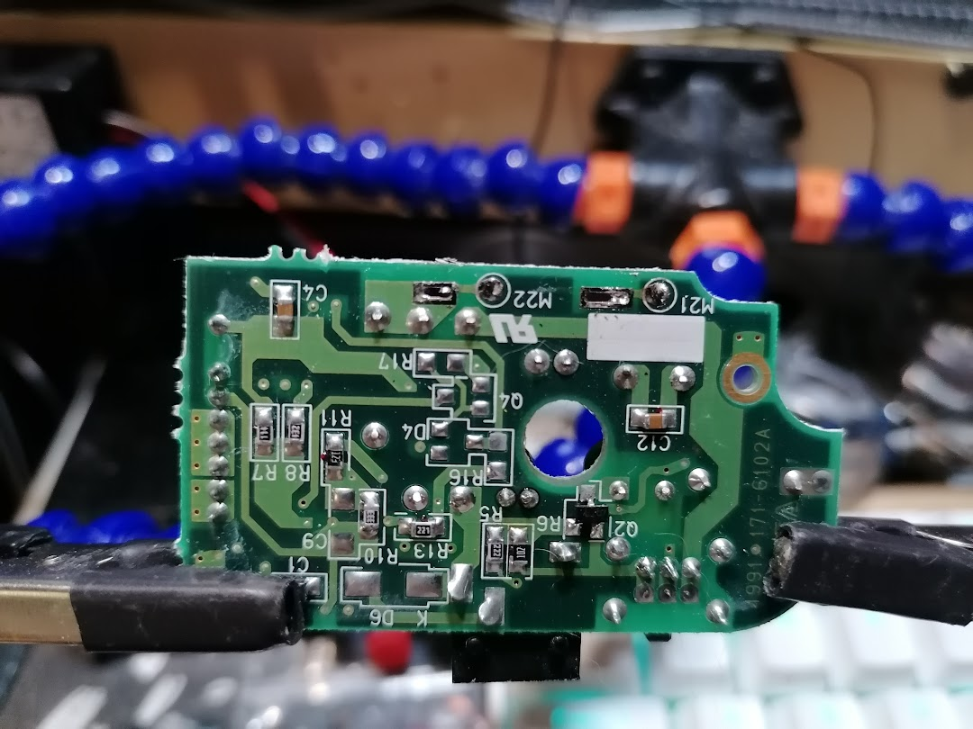


Once removed, you will be left with a lovely, gunky shield to which the battery terminals are adhered to. I had hoped that a liberal wash with some IPA would remove all the gunk from the shield, but it refused to move. This is a testament to the level of engineering that went into these devices - capacitors that are designed to fail (another story...) and foam that will deteriorate. 


To get the gunk off, I ended up having to use a hobby knife to carefully scrape it away, I want to keep the shield intact if I can - its there for a reason. You can use the hobby knife to carefully to get in behind the battery terminals and carefully remove them from the shield. Once that is done, you are free to give it a really good clean. One thing to note here is that IPA wasnt very helpful in cleaning this up, instead I had to use some dedicated sticker remover to really make a difference, I guess Sega really put a lot of effort into making this stuff sticky as opposed to lasting for decades? But then again, how long did anyone really expect an 8-bit handheld from the start of the 90's to be that popular?


Which brings us to the stunning conclusion of this article. I have achieved everything I didn't know I needed to do, but ultimately not the one thing I set out to do, which was clean up those battery terminals. Instead, I now plan to buy in some replacement terminals and replace them before putting the whole thing back together and checking to see if it works or not. To be honest, right now I am not entirely convinced that the amplifier/sound board is going to work. Whilst I was able to remove a lot of the corrosion from the volume wheel, I just dont like the look of it. So I am mentally preparing myself to replace this entire unit as well.

I have also taken a good look at all the capacitors on the rest of the boards, whilst I cant see any that look like they need replacing, there is one thing that most people who know what they are doing with the Game Gear say - you will always need to replace the capacitors. Probably the best thing to do here is to take my component tester and see if I can test some of these in situ to see if they are still in good working order. If they are not, then it may be a good idea to get them replaced whilst I have this thing open...

Wednesday, 8 June 2022

Flashing The ATTiny85 Bootloader

 Recently, I have been looking at the ATTiny85 for use in some tiny projects that I have been thinking about recently. This is an extremely small and versatile microcontroller that can be used in a number of different settings where space or size is a consideration.

You can typically see these used in the Digispark USB Development boards made by Digistump, it is a very distinctive board that you may have seen quite a lot. There are also a number of different ATTiny85 based development boards available on Amazon and eBay, the version I initially got for myself was from Amazon here.

One of the really cool things about the ATTiny85 is the fact that the microcontroller itself is so tiny, as of writing this article I have seen them in two packages, SOP-8 and a DIP-8. It is also possible to buy development boards that have a DIP-8 socket, so that you can provide your own ATTiny85. These are really useful, as it allows you to program your microcontroller before using it in your build.

example of an ATTiny85 development board with DIP-8 socket


When you compare the price of the ATTiny85 itself against the price of a development board, you can see that the boards themselves, even without the microcontroller, cost a lot more. You can pick up 10 ATTiny85's from AliExpress for just under £5 - which is roughly the cost of one development board when you factor in how much shipping could be.


However, this comes with one drawback - the microcontrollers you buy at these prices from these locations will quite often come with no bootloader installed. So even if you follow all the instructions on how to use one of these with the Arduino IDE, for example, you will keep getting a message telling you that the "USB device connected is not working", or something very similar.

Annoyingly, even if you have a socketed development board, you still wont be able to install the bootloader, regardless of having it connected via USB.

So, you may have found this article because you are interested in flashing the bootloader on to an ATTiny85 - or you may be here because you have bought some cheap ATTiny85's from AliExpress and they are not recognised by Windows. This is what happened to me, and these are the steps I took in order to get them into a useable state. You may have also bricked your ATTiny85 and you need to reinstall the bootloader, these steps will also help you to get back into a working state.

To get this done, I used the following:

  • A Windows 10 PC, 64 bit.
  • An Arduino Uno R3
  • A breadboard
  • Some jumper wires
  • A 100nF ceramic capacitor (code 104)
  • a 10nf electrolytic capacitor
  • A DIP-8 socketed ATTiny85 development board
  • A DIP-8 ATTiny85
  • The Arduino IDE

To get started, we are going to need to install the drivers for the ATTiny85 so that we can use it over a USB connection. This is going to be our primary means of communicating with this microntroller for the purposes of uploading sketches to it. Thankfully, we can make use of the drivers provided by Digistump, the latest release can be downloaded from their GitHub. Of the available downloads, we are specifically looking for the AVR release of the drivers, this is important for later on in the process.

There is also a second way of installing the drivers using Zadig, which is a little more complex. I dont really want to go into it too much here, but during this process, you will actually download the files you need to install the driver using Zadig instead.

Next, we need to get the Arduino IDE open and connected to our Uno. This is for a couple of reasons, firstly, we need to change the verbosity of the compile and upload process shown in the console window. To do this, open up the preferences by going to File, then Preferences.

Under the Settings tab, you will find something called "Show verbose output during", with two checkboxes for compilation and upload. Tick both and click OK to save.

Now, we need to make sure that the IDE is setup for the Uno. For most people who are used to doing this they can skip this step. For new users, go to Tools - Board: - Arduino AVR Board - Arduino Uno. Then set the port under Tools - Port. Quite often, the port you need to use is clearly marked as the one used by the Uno:

the Uno I used was clearly visible in the list of ports

If yours doesnt show up like this then just disconnect your board and take a note of what ports are available. When you plug your board back in you will count one extra port. This is the port that your board will be using.

You can also check your available ports in the Device Manager, but this pretty much does the same as checking in the Arduino IDE. As you can see in my example, COM10 is clearly labelled as an Arduino Uno. However, depending on what type of Uno you have, you might see something different.


We now need to do the important bit, under Tools - Programmer, we need to select AVR ISP. 

ISP, or In System Programming, is the method by which we are going to write the bootloader to our ATTiny85 further along.

Whilst we are in the Arduino IDE, we can configure it now for use with the ATTiny85 and development boards based on it. 

Unfortunately, this controller/board is not available from the boards manager by default. So we need to provide a URL for an additional board manager. Thankfully, Digistump have provided just such a resource for us to use. To configure this, we need to add the URL from Digistump to our Arduino IDE preferences, these can be found in File - Preferences. Under the Settings tab, there is a text box where we can add our additional board manager URL, you can add as many of these types of URL as you like of you click the little button next to the text box. The URL we need to enter is:

http://digistump.com/package_digistump_index.json

Once entered, click on OK. Now head on over to the Boards Manager, in the search box type in Digistump. This will bring back all of the boards from Digistump that we just added via the URL, we are specifically looking for the Digistump AVR Boards option, this should be at the top of the list, but this is the one that we need to install.

Doing this will configure the Arduino IDE for use with our chip later on in this guide. It will also install all of the example sketches, which we will also want later on.

Once this is done, we need to verify that our connection to the board is working. We also need to verify that the board is working as well. To accomplish this, we can simply upload the Blink sketch. If everything works and Blink is executing, then the setup for this portion is complete.

We need to grab some important information from within the the write and compilation output in the console window. We are specifically looking for a reference to avrdude.exe and its configuration file. To find this, take a look down the log for Blink.hex - assuming that you uploaded the Blink sketch. Once you have found it, you will see the path for avrdude, for example the path for me was as follows:

C:\Users\rsain\AppData\Local\Arduino15\packages\arduino\tools\avrdude\6.3.0-arduino17

Next up is the electronics, we need to set up some connections from our Uno to a breadboard according to this image:

note the electrolytic connected across reset and ground

A couple of things to note here:

You can use crocodile clips to create the connection from the negative leg of the electrolytic capacitor to the ground rail. It makes things easier, as opposed to trying to stuff legs into single holes.

If you have the electrolytic capacitor installed as above, you wont be able to upload any sketches, it will cause the programmer to fail. This was an issue I ran into when trying to test my Uno was working, you can emulate this yourself, as far as I know it isnt damaging the Uno, it is just keeping it in a reset loop.

The ceramic capacitor is the 104, 100nf mentioned in the parts list above. It goes across the input voltage, however you may be able to get away with not using this, but it is something I did not try out myself as pretty much every diagram that explained this type of configuration used this capacitor.

And thats it, you dont need to do anything more than this to get writing to the chip. The final part we need to concentrate on is getting the bootloader to write to the microcontroller and creating the command needed to write it, along with some configuration.

The file needed to write to the chip can be found here, this is the GitHub repo for Micronucleus. Its a good idea to download the entire repo, or if you have Git installed, grab it on to your machine. We are specifically looking for a file called  t85_default.hex which can be found in micronucleus/firmware/releases/

This repo also contains the relevant .cfg files you need to install the drivers via Zadig.

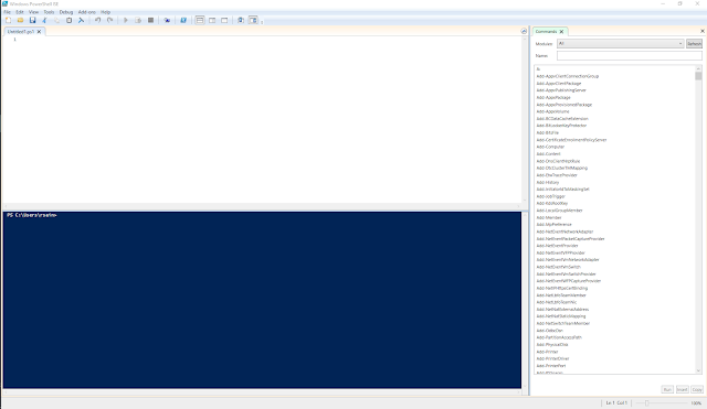
To get started on the command we need to execute to get the hex file written to our chip, I am going to use the PowerShell Integrated Script Environment. This is quite a good tool for putting together complex PowerShell commands by providing a scripting window as well as a PowerShell terminal in one place. This is part of the official PowerShell release from Microsoft, so should be available to you from the Start menu.

On first opening the ISE, you will see something like this:


To give a very brief explanation of how the ISE works, the top section is the script window. Here you can write and execute PowerShell scripts using the standard play and stop buttons that you will find in most IDE's. One cool thing about the ISE is that you can select a portion of your script and choose to just run that instead of everything at once - this can be very useful when trying to find breaks.

from left to right - run, run selection, stop

The bottom window is a regular PowerShell terminal. You will see the results of any script you execute here. You can also enter commands directly into the terminal and execute them if you want to.

Thats pretty much as I want to go into the ISE for now, I think it is a very useful tool to have and is awesome when you are creating PowerShell scripts. Now, we need to prepare a couple of things before we start building the command. Firstly, I am going to copy the t85_default.hex file I got from the Micronucleus Git repo above to C:\temp. This is just to make our command a little shorter.

The last bit of preparation is to navigate to the location where the avrdude executable is found - this is why we needed to download the AVR specific version of the Digispark ATTiny85 drivers earlier on. Again, this is to make the command a little shorter. To do this, we can use the PowerShell terminal in the ISE that we have open. We captured this location a little while earlier, so in the terminal we simply do this: 


Listing the contents of this location will provide you with two folders. The bin folder holds the avrdude executable and the etc folder holds its configuration file. If you navigate to bin, you will be able to test that avrdude is available to you. Despite the fact that I already knew that avrdude was available for use by virtue of the fact that I had already used it via the Arduino IDE, I went ahead and executed it in the PowerShell terminal anyway and got the following:


If you are following along with this article and you can see this, then you are doing fine at this point. If you are getting an error message then close the ISE and open it again as an admin.

Now we know that avrdude is available to use via PowerShell, we can go ahead and start putting our command together. We are going to build that in the script window and I will go over it line by line trying to explain what is happening.

Because this command is going to be quite long, I am going to break it down into a couple of lines. You can do this in PowerShell to any command by putting a backtick "`" before starting a new line. You are going to see this at the end of almost every line we go through here.

The first line is simple, we are just going to execute avrdude:

For the next line, we will use the -C flag. This allows us to provide the current execution of avrdude the location of an external configuration file that we want to use. This is an important step - we need to use the config file that has been set up by the Arduino IDE because we know that this one works. We dont need to create a new one.


On the third line, we are going to configure avrdude to write to our ATTiny85. The first flag I set is -v, this provides a verbose output, I always enable such a thing when I am doing something like this. I recommend it. Next is -P, this is where we provide the port number to use whilst writing to the chip. Choose the one that has been working for you in the Arduino IDE. However, please note that you wont be able to write anything to the chip if you already have an open connection to this serial port, and an open connection can be the serial monitor in the Arduino IDE itself. Next, we are going to set the programmer with the -c flag and set this to avrisp and the baud rate using the -b flag. Finally we set the product with the -p flag with attiny85:


The final thing we need to do with our command is configure the memory options we need to get everything written to the chip, and put it in a usable state. All memory operations are set with the -U flag, read/write, target and expected format. 

Naturally, the aim of this process is to write a hex file to a microcontroller and the first memory operation on this line reflects this. However, I also discovered that we also need to write the fuses on the chip as well in order for us to be able to use it. I actually did a little bit of reading to find out some more on these fuses. They are not fuses in the sense that most of us would think of them, they are not components inside the chip that are designed to fail if something happens. Instead, these are actually bytes that store flags to enable and disable individual features of the chip itself.

So if you were like me, and you were wondering how you can write a fuse to a chip, what we are actually doing is writing something to a location in memory on the chip to configure its hardware.


The first section of line 4 specifies that the type of memory we want to use is flash, w indicates that we wish to write to this memory. The full path to the hex file we downloaded earlier is provided here, the i at the end indicates that this is in the intel hex format.

After this, we have three separate write operations to memory. This is where the fuses are written, the memory type here is instead fuse. Instead of a path to a filename, we see instead a value in hex, and because of this the source format has been set to m.

This setting is for immediate mode, it means that avrdude will either provide input from the keyboard to be written to memory or from the command line. The hex value we see in the command is the location in memory that we need to write to. All the process wants to do is set that location to either on or off, writing to it sets it to on.

And thats it, everything we need to get our chip flashed is ready to go. 

Make sure that your breadboard, chip are connected to the Uno and that you are connected via USB, then just press play from within the ISE and boom, the write process will get underway. That is as long as you can execute scripts on your system... If you have never done anything with PowerShell on your machine before, then the execution of unsigned scripts may be disabled and we need to change this in order to run our script. Basically, any scripts you create yourself will be unsigned unless you sign them yourself. Most of us will never need to sign a script, especially when we are working on things like this at home, so it is easier to change the execution policy.


We can do this by running set-executionpolicy remotesigned on the terminal, this will cause a window to pop up asking you to change the execution policy, click on the Yes button. This will allow you to run unsigned scripts locally, but signed scripts from the Internet.

Now when you run your script, it will execute, hopefully without errors. I cannot preempt all the problems and errors you may encounter. If you have been following along and have not encountered any errors so far, then I would suggest checking over the PowerShell script as this is likely to be where your issue could be. If anyone reading this does encounter a problem and they are not sure about what to do, I would gladly try and help out.

One issue you might encounter is not being connected to the correct COM port, or not being connected at all. The error you get for this is a little esoteric to say the least, however if you get this screen, then double check your connection:


Once the process is underway, you will get a lot of information about the current status of the chip written to the screen. You will see each memory operation that we specified in the PowerShell command get executed against our chip along with its status. The following snippet shows our hex file being written to the chip itself:


And that is it, our chip is now flashed and ready for use. We can try a quick test out here to prove it by uploading the Blink sketch to it. I did this by plugging the chip back in to my development board and opened the start sketch for the ATTiny85, you can get this from File - Examples - DigiSpark_Examples - Start. 

One curious thing about the ATTiny85 is that it shouldn't be plugged in when you want to upload a sketch to it. Instead, you click the upload button and wait until the programmer asks you to connect the device, you will see this down in the console window. Once connected, you will see the sketch get uploaded and, fingers crossed, your development board will have a built in LED that starts blinking.

If you see this, you have just proven that the process you have undertaken flashes a blank ATTiny85 with its bootloader.

If your development board doesnt have a built in LED, instead bring bring one of the pins up high and low with a delay then bring it low. You can measure it with your meter against ground, you should see it go from zero to around 5 volts as the delay changes it status.

And there we have it, a method by which you can buy super cheap ATTiny85's from places like AliExpress and get them usable nice and fast. One thing I did to make my life easier was to build a very basic device that would allow me to do this even faster in the future. With a bit of stripboard and a couple of components, I built myself a little circuit that allows you to flash an ATTiny85 using the process above. It is nothing fancy at all, it just replicates what I had on the breadboard, but it means that all I need to do is wire it up and connect it to an Uno to get going, plus I was a little bored one day.

the chip in this diagram should be socketed, but there was no asset to represent this


This is a very simplistic design, but it helps remove the annoyance of having to connect the electrolytic capacitor to the Uno itself.

IC1 represents our ATTiny85, the application I use to generate these images doesnt have anything for an 8 pin socket, so a bit of imagination is required here. Naturally, this is where our chip goes.

C2 removes the the electrolytic capacitor we had connected across ground and reset on the Uno itself. Now we just need to connect two cables back to the Uno. The bottom connection goes to reset on the Uno and the upper connection goes to ground on the Uno.

The connections for J1 are just the same as they were on the breadboard. Starting from the top we have:

  • Vin
  • Pin 13 on the Uno
  • Pin 12 on the Uno
  • Pin 11 on the Uno
There is only one connection from J2, the top connection is connected to pin 10 on the Uno.

This allows me to have something that is purely dedicated to flashing the bootloader on to an ATTiny85 whenever I need to. Naturally, I could have made the connections a little more intuitive, and there is a way you could use the same board for uploading sketches to the chip - but I want this to do one thing and one thing only, and that is to flash the bootloader. I also want it to be a process I have to think about, so that I dont wipe out a bootloader on a chip I have a working project on, it needs to be an intentional move to stop me from messing up.

If you go ahead and create something like this for yourself, make sure that you cut the tracks under the socket for IC1. This is stripboard, so everything is connected on one axis. Whilst this is very useful, you will need to cut those tracks for the build to work.

This is what mine ended up looking like:


Just a point to make here about the build, those header sockets I am using there are the round type instead of the square type. They seem to be a lot easier to work with, especially when you are trying to squeeze jumper wires on to small builds. They are quite often cheaper as well:


Now that I am able to write the bootloader to my chips, I can get on with experimenting with them and hopefully using some in a couple of projects that I have in mind. If anyone has tried the process I have described above out, and encountered a problem that they cant get passed, I will gladly try to help out in the comments, or by even adding a new section or two to this article.

Also, it may be the case that Micronucleus is not the only bootlader that can be written to these chips. Recently, I have been reading about this really interesting project called V-USB...

Here are the links and resources I used to get this mini-project done:

Digistump GitHub:

https://github.com/digistump/DigistumpArduino/releases

Micronucleus GitHub:

https://github.com/micronucleus/micronucleus

Arduino IDE downloads:

https://www.arduino.cc/en/software

Zadig:

https://zadig.akeo.ie/


Tuesday, 3 May 2022

Trying To Repair The Batteries On My Drone

 A couple of years back I found a drone, complete with all its accessories and bag etc in the trash. Someone had thrown it away because one of the propellers didn't work, and the reason it didn't work is because one of the wires connecting it to its motherboard had come loose. After 30 seconds with a soldering iron and a meter, it was back up and running again, and I had a complete drone with kit for free.

Since then, it has taken a few more knocks - one time it got stuck in a tree after an unexpected gust of wind and came crashing to Earth whilst I went to get a long pokey stick to help it down. But overall I have been able to keep it in good working order, despite some cosmetic damage.

Sadly though, after some storage over the winter, I have discovered that the batteries for both the drone and its controller now seem to be unable to take a charge. I did think that this could happen for the controller, as the battery cannot be easily removed from it - but the drone battery pack is removable for recharging and storage. It was disconnected from the drone when it went into the cupboard in December, so I am a little unsure as to why it is behaving this way...

I am going to start with what I think is the easy win right now, the controller.

Partially disassembled controller

The first thing we need to do is extract the battery from within the controller itself. It sits within a cage that also has the antenna hot glued to it. When I first rescued this drone, the controller had these big, flat, folding antennas on each corner. Once I got into the controller itself, I discovered that they were ornamental - they were just pieces of plastic, so I took them off and binned them.

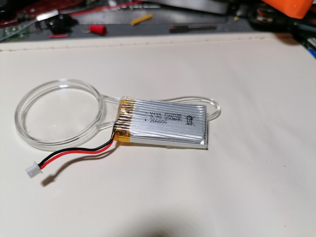
With the battery out, I need to measure its current voltage. As the label suggests, this is a 3.7 volt 350 mAh battery, so we want to see something near this value when it is working correctly. As I am typing this, I haven't measured anything, so at the present time I think it is going to be pretty low...

The controllers internal batter


After measuring the battery on the meter, I was very surprised to discover see 4.26 volts come up on the display. So much so that I measured it again on a different meter - and got the same measurement again. This is very strange, one of the features on the controller is a strip of LED's that provide a battery status. When connected to the power, they also act as a charge indicator. Before opening the controller, the LED's were flashing in a specific pattern, but with only two of them lit. As one of them was orange, I assumed that this was the charge/on light.

This means that it might not be an issue with the battery charging in the controller, it could indicate a larger problem with the controller itself. I dont know if these types of battery can be "over-charged", or if the existing battery is damaged, so its probably a good idea for me to go ahead and replace it any way. And if I am going to replace it, why dont I increase the battery capacity at the same time? On the original battery I got about 20 minutes of flight time. The drone itself can last a little longer, but having a higher capacity battery on the controller would be incredibly useful.

Going through my current battery collection, I discovered a 3.7 volt 300mAh which shares an almost identical physical configuration to the original battery. However it is a lower capacity battery at 300 mAh, which would mean even less use time on the controller itself. 

But, I have quite a few of these batteries, so why not use more than one to increase the capacity from 300 mAh to 600 mAh?

In pretty much all cheap electrical consumer products, we see multiple batteries being used. Typically these are an even numbered combination of AAA, AA or D cell batteries. These batteries normally provide something between 1.2 and 1.5 volts, however the devices they power often require voltages higher than this or capacity that exceeds that of one single cell.

This is why we have to put batteries in these devices in specific combinations, and each device will require either one of two configurations, those being parallel or series. Connecting batteries in series increases the available voltage, so connecting six AA cells in series would give you 9 volts, depending on the cells. Connecting the same number and type of batteries in parallel would give you a voltage between 1.2 - 1.5, depending on the cells, but the capacity will have increased six fold.

To connect two or more cells in parallel, you simply connect the positives to the positives and the negatives to the negatives. With this done, you have increased the capacity by creating a battery pack. To connect the batteries in series, you connect negative to positive etc. Once done, you will have increased the voltage by again creating a battery pack. This is the reason why we place batteries in devices pointing in a specific direction. 

For my purposes though, I will be connecting two of my 300 mAh batteries in parallel for the reasons described above. The following image best describes what I need to do in order to achieve this:

Connecting batteries in parallel with strip board

Unfortunately, my two replacement batteries cannot be squeezed into the existing battery cage - and I dont want to make any physical changes to it as it acts as the antenna holder as well. However, there does seem to be plenty of space in the controller for these to be held in place with some command strips. However, I can use the holder to take care of a piece of stripboard to handle the connection to the controllers mainboard.

I actually find that drawing things out on a piece of strip/perf board helps me with routing tracks and any jumper wires I might need to put in. I also dry fit the components to help me realise the orientation and correct placement for them. Using Fritzing, the application I used to generate the previous image, helps a lot. But when you cannot find the same part you are using for real in its menus, getting your actual board realised needs some planning. I used some copper tape to indicate where I need to join tracks, and have also marked where tracks need to be cut. The copper tape isnt great as a conductor on its own, but you can use it for a continuity test. There would also be a jumper on the reverse to join the two upper tracks, however I have omitted this. 

The completed battery board ready to go into the controller

With the board finished and all of the relevant connectors soldered into place, I was able to fit this into the battery cage in the controller. The batteries were fitted into the shell of the controller and I rebuilt it enough for it to be able to go on charge. I was pleasantly surprised to see that once it was connected up to a USB C cable, the controller began to charge the batteries. So I went ahead and put the whole thing back together.

the battery board and batteries installed in the controller

After about an hour, the charge light went off and I decided to turn the controller on to see how we were doing. 

Sadly, even after replacing the batteries, the controller refused to work correctly. It was showing the same flashing LED's - which I think must be an error code - as it did with the previous battery.

So thats one dead controller...

Next up is the main battery for the drone itself. This charges via a USB adapter that was in the case when I found it. This is pretty essential, as without it I would have been pretty much unable to charge the main battery. Whilst charging, the LED's on the battery are supposed to light up and indicate the charge level. However now, they are completely dead.

The battery is marked as 11.1 volts with a capacity of 1600mAh. It also states that it can deliver 17.76 Wh of power. These are pretty capacious batteries for two reasons - they supply power both to the avionics and to the propellers. The propellers will use the majority of the available power for achieving flight.

I hooked the charger up to my USB meter, this is a really useful tool for looking at what takes place over a USB connection. It can be used to measure the voltage, current and power being used by a device that charges over USB as well as monitor the same over the D+ and D- lines. However I noticed that whilst the batter was connected to the charger, there was no power draw. I would expect to see something around 1.5 amps if this battery was charging correctly. This is because the charge cable states it has an output of 11.4 volts and 1.5 amps.

USB meter used to monitor power draw


The only other thing I could do at this point is to check the internals of the battery itself. Within, I found that there were three 11.1v cells connected together, given the parameters of the battery that I already knew I assumed that they were connected in parallel, in the same way I approached the controller. But of course, this batter has circuitry that is much more complex.

I think its probably a good point in time to state that working on a battery like this is not a trivial matter. The risk of shock is high, and whilst not that dangerous to you, it could be painful. However, the risk of rapid battery failure in the form of smoke, flames and explosion - and I am not kidding here - is pretty high when you are dealing with a something like a battery pack that will no longer charge. Its always a good idea to have a flame proof container like a biscuit tin, or oven pan to hand so that you can quickly dump a failing battery. One time I opened a battery pack that had taken a knock ended up with one of the cells rapidly expanding and becoming scorching hot with seconds.

The exposed battery pack


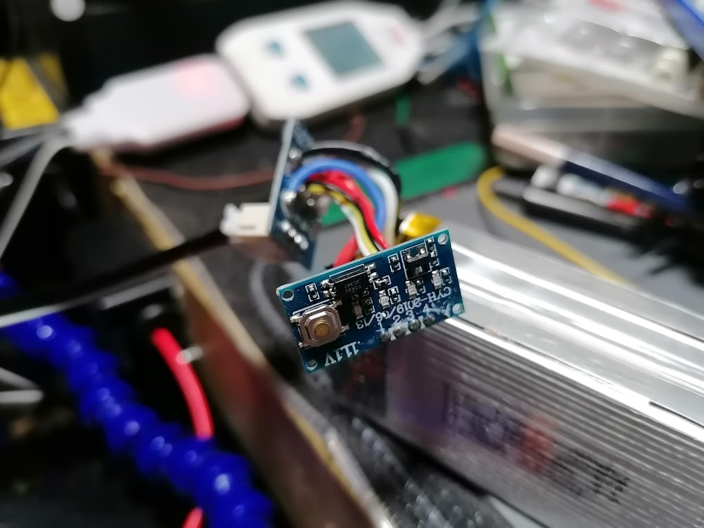
After getting the pack out, I checked for any obvious damage to the cells themselves. If you see a LiPo with damage to the edges then be wary, its often ones that have been bashed on the edged or corners that like to go nuclear. Plugging it back into the charger allowed me to probe around some of the connections.

This helped very little other than to indicate only one of the cells appeared to have any charge, and this was at 12 volts. There was no sniff of power anywhere else on the board at all, none to the LED's or the single button provided.

The battery packs circuitry


So sadly, it looks like the charging capability of the battery itself has ceased to work. It is odd that both batteries would go at the same time, especially after being stored in the same way. But I needed to remember that this is a piece of equipment I dug out of the trash and got working again, I dont really know if the initial problems were caused by something else, like a formidable crash.

Where does this leave me? Well, with no drone any more it seems. Unfortunately, I haven't been able to repair any of the damage to my drone at all. Its pretty hard, if not impossible, to find replacement parts as well. This was a mass consumer device made with some specific parts, I can take some bits and pieces off the shelf as replacements, the propellers and motors etc, but the charging is handled by the battery - the cost of one of those right now is almost as much as buying a new drone. So I wont be doing that. Also, the mainboard for the drone is not able to be customised, I cant replace the firmware or anything else on the board at all. Right now, its dead.


Did I learn anything? Well, initially this want an exercise to learn anything new in particular - if anything I have come away from this with more questions about batteries as it turns out that I know less about them than I thought. But one thing I was able to improve on here was my skills in diagnosing potential problems. A list of checks was written down as well as me working back from where the power came in with a meter to see where things went wrong first.

Which is great etc, but now I just dont have a drone 😞


Saturday, 5 September 2020

Serial Communications with Arduino Part 2 - Software Serial Ports

 Last recently, I put up a short post on how we can use Arduino to read data from a device. Cunningly, I made the process so simple (mainly for myself) that I neglected to actually use an Arduino.

So, in this post I will remedy that by providing an example on how to read data from a device using serial communication at the start, then move on to writing to the serial port.

In the last post, I gave an example of how you can connect a USB to TTL adapter to a device and read its data. This time round, we are going to use the UNO R3 to act as our USB to serial adapter. To do this, we are going to be using the following

  • 1x    breadboard
  • 1x    Arduino UNO R3 
  • 1x Neo-6M/GY-GPS6MV2 GPS Module
  • 1x CH340 USB to TTL adapter
  • Jumper wires

The proposition is quite simple; we want to send the output of the GPS module to the board over a serial port. Unfortunately, I have not found a way to simply connect it to the TX/RX pins on the board itself and have it output data. So, to accomplish this we need to create a second serial port to handle the incoming stream of information from the GPS module itself and we need to create that port in software.

To do this, we are going to have to use the Software Serial Library.:

1:  #include "SoftwareSerial.h"  
2:  SoftwareSerial ss(8, 9);  
The first line references the library we need to use in this program. If you get an error when compiling this code, you might want to check that you have this library installed from within the Library Manager.

The second line is simply us creating a new software serial port called "ss", the numbers following represent the RX and TX pins on the board.

Next, we have to set up our ports, this should be familiar to anyone who has been using the Serial Monitor from within the Arduino IDE: 
1:  void setup() {  
2:   // put your setup code here, to run once:  
3:   Serial.begin(9600);  
4:   ss.begin(9600);  
5:  }  

Here we can see that on line 3 the hardware serial port is started with a baud rate of 9600 - this is the speed at which the port is reading/writing at. Line 4 is almost exactly the same, however this is the software serial port that is being started this time, note that we are also starting it at the same baud rate.

From reading up on using this library, it seemed that 9600 was the highest baud rate to go for and still have a stable connection. The GPS module can work up to 115200 baud, however when I configured the serial ports to use this speed, nothing happened.

Next up, we have the main executing of the code itself. We read the data leaving the GPS module on its TX port on to the boards hardware RX port and vice versa: 
1:  void loop() {  
2:   // put your main code here, to run repeatedly:  
3:   if (ss.available())  
4:    Serial.write(ss.read());  
5:   if (Serial.available())  
6:    ss.write(Serial.read());  
7:  }  

Line 3 checks to see if the software serial port is available, if it is then the hardware serial port then writes whatever the software serial port is reading on line 4.

Line 5 does the opposite, if the hardware serial port is available the software serial port writes whatever the hardware serial port is reading - which happens to always be whatever the software serial port is reading due to the structure that we have created.

Think of the above as an exchange - the hardware serial port is empty until it reads the incoming message from the software serial port. Once it has that, then both ports will have the same message.

Make sure you have your serial monitor running when you upload the code, you should see something like this:


The full listing for the code will be at the bottom of this post.

At the start of this article I mentioned that I used a CH340 USB to TTL adapter for debugging. This is because I had a fairly hard time getting the software serial port actually doing what I wanted it to do, quite a few of the articles I had read on the subject provided examples that simply did not work so I began to think my GPS module had become damaged.

So, to verify that the GPS module was working whilst the board was running the code, I connected it in series with the wires going from the GPS module to the board.

This let me run putty to make sure that I was getting something from the GPS module itself and make sure there was an incoming message for the board to do something with. It was actually quite helpful to do this while figuring out my problem. 

The setup, minus the USB to TTL adapter, looks like this:


If you are trying this out for yourself, then hopefully you are seeing a nice barrage of NMEA sentences scrolling across your serial monitor.

However, if you are seeing nothing, then try swapping your RX/TX pins on the board itself. You might have gotten them mixed up - I certainly did a couple of times.

SoftwareSerial is not the only library available that can do the same thing. Another, very popular library you can install is AltSoftSerial. Syntactically, it is almost identical to SoftwareSerial and supports a wide arrange of MCU's and development boards. You can also use a mixture of different libraries to give yourself multiple serial ports to work with, should you need to, for example if you had a number of devices that provided data in the same way as the GPS module you will need to have more than one serial port configured to a set of pins. That way you will have an uninterrupted flow of data from each device on its own serial port.

So what does all of this mean? Well essentially it is just a description of how you can easily set up a couple of serial ports to share data. But in this specific context, where could we take the build next? We are using a GPS module and we can see the NMEA sentences that it is receiving. We also know that each sentence begins with a $, so we could easily read the sentences into an array or object in order to process them further.

From looking at the output, we can see that there are six distinct types of sentence being received, or at least the module is trying to populate the contents of six sentences with data from the GPS constellation, with that knowledge we might be able to do something useful with that data...

The full code listing for used for this article is as follows: 

1:  #include "SoftwareSerial.h"  
2:    
3:  SoftwareSerial ss(8, 9);  
4:    
5:  void setup() {  
6:   // put your setup code here, to run once:  
7:   Serial.begin(9600);  
8:   ss.begin(9600);  
9:  }  
10:    
11:  void loop() {  
12:   // put your main code here, to run repeatedly:  
13:   if (ss.available())  
14:    Serial.write(ss.read());  
15:   if (Serial.available())  
16:    ss.write(Serial.read());  
17:  }