Wednesday, 5 August 2020

Serial Communications With Arduino

 This article is going to cover the topic of serial communication between an Arduino and another device. There are plenty of very good examples in the Arduino IDE that help you get to grips with the basics, but for this one we are going to do something that could actually be useful. To do this we will be using the following:

  • Neo-6M/GY-GPS6MV2 GPS Module
  • Arduino 2650 MEGA
  • CH340E USB to TTL adapter
  • breadboard
To start off with, we can illustrate a very simple example of serial communication taking place. The GPS module we have here is a self contained unit, once it is powered up and has its antenna attached, it will start to look for satellites and begin printing out its status via serial communication. I don't need to do anything at all for this to happen, however in order to read this data, we must connect a TTL/serial terminal to the module itself.

USB to TTL on left


This is where the USB to TTL module comes in to play. We can attach the serial port on this device to the serial port on the GPS module and connect the lot up to a computer using a USB cable. Once done, you will be able to use a terminal to connect to the serial port and view the raw GPS data in the form of NMEA sentences.

So, lets get started on the easy part of connecting the USB to TTL up to the GPS module. If you don't already have pins installed on these modules, go ahead and solder them in now, once done you want to put them side by side on the breadboard, its probably a good idea to use the outer most pins on the edge to seat these components.

Before doing anything else, lets make sure that the USB to TTL adapter works, and that you can use it. To do this, connect a USB cable to it and your computer, if this is the first time you are doing this your OS may tell you it is being installed, so wait for that to take place. If not, then it should just give you the noise to tell you it has been connected.

We can verify the connection by looking at the available ports your OS has available. On Windows, there are a couple of ways to do this. The best way is to go into Device Manager and look under "Ports, COM & LPT". You will see your adapter listed here if it is present, mine looks like this:

USB to TTL adapter highlighted

Note that port number down, it probably wont change and you will need it later. For now, we can disconnect the USB cable and get to work setting this up.

We need to power the GPS module, it is 5v tolerant but for right now lets run it at 3.3v - we can get this from our USB connection. Simple connect a wire between the 3V3 pin on the USB adapter and the VCC pin on the GPS module. Connect a ground wire accordingly.

Next, we need to connect the TX and RX pins to one another. When you are trying to transmit data between devices like this you need to connect these pins to their opposite.

This means you connect RX to TX and TX to RX. 

Doing so means that the device transmitting is always transmitting to a connection that is receiving and vice versa. So lets connect the TX and RX pins together, take a wire and connect TXD on the USB adapter to RX on the GPS module. Next connect the RXD pin on the USB adapter to the TX pin on the GPS module.

You need to be careful that you do not accidentally connect one of the serial pins to a power supply by mistake, this could damage your components.

Once you are happy with your connections, you could have something like this:


All we need to do now is hook up the USB cable and connect to the serial port. The best way to do this if you are using Windows is to get hold of PuTTY. Its a fantastic, free SSH and Telnet client that pretty much the entire world uses I think, you can download it from here.

So, to get this up and running, open up PuTTY. You will be greeted with a screen like this:


Make sure you have Session selected under Categories on the left, this is the highlighted field in the top left. Then select the Serial radio button, highlighted on the right. You will need to enter your COM port number here, I have entered 12 as this is the port number that has been assigned. Once I am sure everything has been done, I go ahead and click on Open.

And hey presto, you start getting GPS data back in the form of NMEA sentences, just like this:


This data will keep scrolling for as long as you keep power flowing through this circuit. As time goes by, the module will receive more and more data from the GPS network and all of those missing fields will be populated.

And all of this has been achieved without writing a single line of code.

So how useful is this? Well, in general terms, if you have a device that pins or pads designated as "UART" or "Serial", then you stand a very good chance of hooking them up to something like PuTTY to see what, if anything, is being sent out of the device. This can be really useful if you have a faulty device, sometimes they write out the error state on a serial port which can be read from another device. You might even be able to write data back over that connection - for example I have a NAS that is faulty at the current time, I have connected it up in this way to see if there is a specific error message, or any other info being written to the port. Unfortunately in this case, nothing useful turned up - but I did discover that I can flash the device using ICMP - which will be really useful once I figure out how to do it.

But in the context of the module used in the example above? Well, the data we received from it were standard NMEA sentences. To a human, they don't mean anything, we cannot really decode them without help. So with some code, we can consume those sentences and turn them into data that we can use easily, like coordinates and other measurements that we can easily comprehend.

But this is a topic for another time...

Sunday, 5 July 2020

Using Transistors As a Switch with Arduino

 Recently, I have had reason to look into switches and how they can work with Arduino, and other popular MCU's.

This is part of a larger piece of investigation that is looking into buttons, sliders, potentiometers, switches etc as inputs whilst I think about how to make my own keyboard.

Of course, everyone has heard of a transistor. We all have some form of awareness as to how important they are with regards to the evolution of technology and computing. But what is a transistor really? Anyone with a background, or an interest in computing will probably tell you that they are used to calculate things on a CPU, and they are correct - but this isnt what transistors are limited to.

I am not going to go into the science of transistors here or how they work on a microelectronic level, there are plenty of other blogs and articles who have done a much better job than I could ever do. What I am aiming to do here is to give a quick guide on how to pretty much use a transistor as a switch, how to connect one up and how to control one in the code.

Transistors basically can do two things; they act as switches and they can help amplify signals. And they do this by controlling the current flowing through them. However today, I am only going to be talking about how they can be used as a switch in this article. You may be asking why would you want to use a transistor as a switch? There are no physical controls, so you would need to programmatically control it - and that's the beauty of using a transistor as a switch.

One really good example of how this can be used could be this - you have a light somewhere that you want to turn on when it gets dark. You build a circuit with a lamp, and a light sensor. When the state of the light sensor reaches a certain point, you then want the lamp to light up. So you can use a transistor to act as the switch to do this.

Naturally, all of this would require an MCU of some type as well as some code, but it really is a nice little example of a potential application.

One of the neat features of using a transistor as a switch is, depending on your transistor, that you may be able to switch on a circuit of a much higher voltage. This is because a lot of transistors are capable of handling a lot more voltage because of their amplification abilities.

Transistors typically come with three pins, which are cryptically called:

  • Collector: This is normally the current you are trying to control.
  • Base: This is normally the current you use for the switch. It controls the bias on the transistor.
  • Emitter: This normally goes to ground.
For the examples below, I will be using the following components:

  • 2x 1 kohm resistors
  • 1x red LED
  • 1x PN2222A transistor
  • 1x Pro-Micro/Arduino Nano MCU

Here is an example diagram to help visualise this:


On this breadboard we have a transistor acting as a switch to control the LED. When 5 volts is applied to the power rail, the LED will light up, if I remove the transistor from the circuit then apply power, the LED would not light up.

Why is this? Well, to explain this, lets look at the names of the pins in relation to the connections in the diagram. 

Starting from left to right, we have the collector first on pin 1. This has the LED connected to it, with a 1K resistor running to 5 volts. This part of the circuit represents the current we are trying to control.

The middle pin, pin 2 - we have the base. This is the switch itself, when enough current is passing through it, the switch is closed. When there is insufficient, or zero current flowing through it, the switch is open. This controls the flow of current through the collector - this means when the switch is closed, current flows through the collector and the LED lights.

On the right, we have the third pin, which is tied to ground.

If you construct this circuit, there are two ways to test it. Firstly, remove the transistor from the circuit and apply power - the LED should be off. If it is on, then you are passing power to the LED without the transistor controlling it.

Second, disconnect power from the base, this should turn off the LED. If it doesnt, then again - you are probably passing power to the LED outside of the control of the LED.

Now, the above shows a transistor controlling current to an LED using 5 volts, but remember when I said they can also be used to control the current in circuits that require a higher voltage? We can create an example of this as well, but this time using 3.3 volts to control the transistor whilst still using 5 volts to light the LED:

All that has changed in this example is that we are now applying 3.3 volts to the lower power rail as well as 5 volts to the upper power rail. When the power is connected, the LED will light up.

One point to note here is that using a transistor in this setting is rather pointless. All this circuit does is provide power to an LED. This can lead to some confusion  when building such a circuit for testing or educational purposes.

So how about we create the classic "blink", but this time using our transistor? To do this, we are going to need to use a micro controller, for this example I am going to use a Pro-Micro/Arduino Nano using 5 volts. This means we can keep our initial breadboard design the same, more or less.

All we need to do is alter the way the transistor is biased. Instead of simply being powered directly from the power rail, we are going to connect it to a GPIO pin:


This is the same circuit as the one I initially built. It is orientated differently to accommodate its one difference, and that difference is how we are controlling the base on the transistor.

Previously, we were simply providing it with current, which caused the LED to be illuminated for as long as power was available. However in this example, we have connected the base to pin 2 on the Nano. Unless you make it happen, pin 2 will not be high, which means if you create this circuit and power it, the LED will not light up.

So, on to the the classic "blink", to achieve this we need to write a couple of lines of code, the whole thing is this:


 1
 2
 3
 4
 5
 6
 7
 8
 9
10
11
12
13
void setup() {
  // put your setup code here, to run once:
  pinMode(2, OUTPUT);

}

void loop() {
  // put your main code here, to run repeatedly:
  digitalWrite(2, HIGH);
  delay(1000);
  digitalWrite(2, LOW);
  delay(1000);
}


The setup for this is simple, we just need to define the pin we are going to use to control the base. In the diagram we have it connected to pin 2, so that is what we define here. We need this to be used for output, as we will be sending a signal to the transistor.

The main body of the program should be familiar to anyone who has tried out the blink sketch that is used to test out various developer boards. We simply take pin 2 high for a couple of seconds before sending it low for the same amount of time.

This basically opens and closes the transistor as if it were a switch, if you try this out for yourselves, you will see the LED blinking on and off every couple of seconds.

Now, lets get in to some specific points that are worth mentioning:

Using resistors is essential. Not putting a resistor across a transistor in the way I have shown above can often cause your transistor to melt, it certainly did for me unless the ones I had were also defective. It is important to note that the resistors you use should be of the appropriate resistance for your load - it wont always be 1 kOhm.

The examples above use an Arduino Nano, but everything here is also compatible with the cheaper Pro-Micro developer board. The only difference between the two boards is that one provides a 3.3 volt rail and the other doesn't.

Using a GPIO pin to control the biasing of a transistor is the win here. The state of the transistor can be governed by the state of a separate sensor(s), the result of a programmatical state or pretty much anything that is capable of changing the state of that pin.

For me, it was fun but a little frustrating learning about how transistors work. Writing this blog entry has been part of my learning process and perhaps someone will find it useful in the future themselves :)

Friday, 3 July 2020

Creating a 5 Volt DC Power Supply

 Just over a year ago I bought myself a robotics experiment kit from Amazon to play with during some downtime.

Naturally, a lot of us have had a lot of spare time (sort of) on our hands lately. So this gave me the opportunity to get this kit out and start playing around.

On opening it up, I discovered that it wasn't just a robotics kit, it was actually an Arduino based experiments kit. For those of you who don't know, Arduino itself is an open source hardware electronics platform. The open source bit is how their kit works, naturally you need to buy the hardware itself - or if you are skilled enough, you can make it yourself from the schematics and tools Arduino provides.

You can get more information about Arduino gear on their site as well as browse their store. I need to point out that I am in no way affiliated with Arduino, or get anything for writing about them.

In fact, it is often cheaper to browse eBay for Arduino clone boards than it is to buy the official ones, but that is a story for another day.

Now, back to the point. Once I had finished all the experiments described in the kit, I decided to try my hand at building some actual devices for myself. Of course at this point, I wasn't quite sure what to build, but I knew one thing, what ever it is I decided to build, it would need to be powered in some way.

One of the interesting things I discovered working with these electronics is that pretty much everything, including consumer electronics, runs from a DC power source. This means when you are building something, powering it from a wall outlet or a battery is usually interchangeable. The work you have to put in is how you condition this power source (for want of a better phrase).

To do this, we need to use a voltage regulator. A voltage regulator is an electronics component that is designed to control the forward flow of power from a power source, like a USB lead or a battery, onwards to your circuit. Wikipedia has a very good article on the subject here if you are a newbie like me and want to learn some more. In their simplest form, they will have three pins, voltage in, voltage out and a ground pin.

When building my own power supply, I wanted to use the same voltage regulator that came with the micro controller that came in my experiments kit - this was a Mega 2650. In order to find out where the voltage regulator might be (don't forget, my knowledge of electronics is very basic at this point) I referred to the boards schematics. I don't really understand how to read these very well at this point, but was easily able to see where the power for the board comes in, you can take a look at them here the power input is in the top left hand corner. After googling the name of all the components, I found what I was looking for, the MC33269D 5. This little guy is intended to take a DC current through the barrel connector and drop it down to 5 volts DC for the board to operate. Most people will never use this method though, as most of us will be powering the device via USB, which will also give you 5 volts DC.

However, when I went to look for this component on my board, it was missing. Mine seems to come from a company called Elegoo, which are a good place to get hobby electronics kit, so wasn't a cheap clone. In its place, we have an AMS1117-5, after a quick search I discovered that this is also a 5 volt DC regulator, I also found the same component on a few other boards I have. So it made sense to build my power supply around this component, it is cheap and readily available from places like eBay, Amazon as well as Mouser etc.

Another new thing for this bit of work that I am using is a tool to help me plan and design my build. Previously, if I was working on a largish experiment on the breadboard the most work I would put in to designing something was maybe a scribble in a notepad. That's fine when you can change any wire or component when ever you like, but when you are soldering things down you want to be 100% sure that you are putting the right thing in the right place and its orientated in the right way. Otherwise you can ruin a whole build and you may need to start from scratch... This is the voice of experience talking.

When looking for examples of Arduino circuits, you will often run in to these wonderful little images that simulate the layout on a breadboard. I wanted to use this in my posts going forwards, so I tracked down the tool used to make them. Again, I am not affiliated with this company, and I dont get anything from them and you need to pay for this tool, but it is available from Fritzing. In my humble opinion, the license is very cheap for what you get and for those who are inclined, you can download the source for free and compile it yourself. However I am not going to go into that here. This isnt going to be a tutorial on how to use Fritzing either, its a really easy to use package and is essentially drag and drop. As a tool for helping me with my little builds, it has been extremely helpful and has enabled me to learn more about what it is I am doing.

So, lets get started by creating a new design and putting a voltage regulator on it. Fritzing doesnt have a dedicated symbol for the AMS1117, so a search for this will give you pretty much nothing you can use. However if you search for 1117, you will get something called a "V_REG_LD1117VXX". This will do for the purposes of design, layout and even construction, depending on how you build this. The LD1117 precedes the AMS117, so lets get this out on to the board:

Before we go any further, we need to take a step back and address reality here for a second. If you found this article after looking for ways to create a 5 volt DC power supply for real then we need to talk about the package the AMS1117 family comes in. For the sake of illustration, I am using a TO-220 package to represent the voltage regulator. In reality, the AMS1117 family are all in the SOT-23 package (to the best of my knowledge). This is a lot smaller than the one pictured here and while it is possible to solder one of these by hand to some 2.54mm pitch protoboard, you are not going to be able to use one on a breadboard easily.

However, you can get adapters that will allow you to mount pins to a SOT-23 package, these are basically SOT-23 to DIP adapter plates. You can get them from all the major stockists online, but I found the cheapest place to get them so far is eBay, an example of some can be found here. This is what an AMS1117-5 looks like when it has been installed to one of these adapters, you can see how this will make things easier:


AMS117-5 next to SOT 23 to DIP adapter


You can use some flux to hold the regulator in place for soldering.


Try to solder one of the outer pins first. This will make the rest easier.


To finish off, you just need to add some 2.54mm pitch header pins and you are done. An easy way to solder components like this is to use a breadboard for support:

Some extra headers are laid flat at the other end for support.


Get some flux on and get one of the pins soldered into place, you can make sure it is square here before continuing to solder the remaining pins. Don't worry about getting it done perfectly at this point, we don't want the plastic on the headers to melt.

If you need to, go back over the joints to make sure they are even and then you are done. You should end up with something like this:


If this is the first time you have done something like this - well done, you just made your first very own component! You can now go on and use this in your own breadboarding as a 5v DC voltage regulator!

Now, back to the design. I need to make a few changes here to the symbols properties in order to make it more visually relevant to the build. The changes I make are as follows:


Now we need to push some power into this, you could assume that it is coming from a 9 volt battery, such as a PP9. Technically, you could connect the plus and minus pins from the battery directly to the battery and it could output a 5 volt supply, however that's not really how it works. We need to get a few more components in there before we can actually start using this. To start with, we want to make sure that power cant come back through the circuit and damage the battery - or whatever power source you are using. So we need to stick a diode between the battery's cathode, positive line, and the forward flow to the voltage regulator. A diode is essentially a one way gate, a current can flow through it one way, but not the other. This makes it ideal for protecting your power source.

With this done, I need to add in some capacitors. If you take a look at the NCP1117-5 datasheet, which is also very similar to the AMS117 family, you can see a breakdown of the output capacitance vs the  equivalent series resistance (ESR). Output capacitance here refers to the capacitors we need to put in to the circuit as power leaves the voltage regulator and from looking at the graphs on page six of the datasheet, we can see that a 100uf electrolytic capacitor flowing to a 100nf ceramic capacitor will provide what we need. This will help smooth out the flow of power as it moves through the circuit - I am also going to do the same thing as power goes in to the voltage regulator as well for the same reason.

Next up is to simply add something in to indicate that there is power running through the circuit, this can easily be done with a 1k resistor and a red LED. The completed breadboard could look something like this:


Naturally, this probably isnt the best way to illustrate the layout. I am still getting used to the tool, but it certainly makes you think about what you are doing before you do it and why you are doing it. For the above to work, you simply need to provide a DC power source greater than 5 volts on one end. The LED will light up to show the circuit is working, to test it you can get your meter out and measure the incoming supply before it hits the voltage regulator to see what is being fed into it. The design above ends in a screw terminal providing both positive and negative, you can measure here as well to see that you get a steady 5 volts, or there about. 

Don't worry if it is slightly under or over, what we need to check is the stability of the voltage. If you are seriously over or under 5 volts, then it is highly likely your regulator is either broken, or an incredibly poor quality copy.

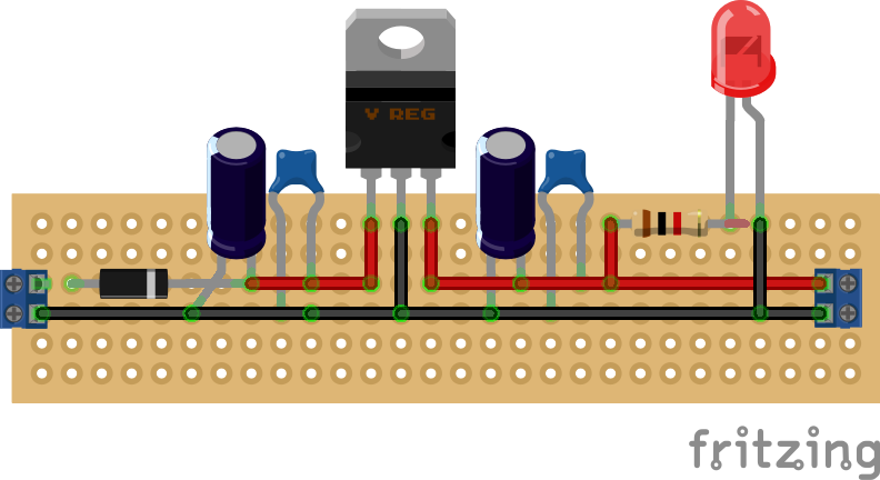
Now, if you want to, you can go ahead and build this on a piece of protoboard, but - before you do, why not model that in Fritzing as well? You can actually design on protoboards of different types in this application as well as use a breadboard, so if you are like me, you can design what you want on screen first before you commit it to the board. As long as it has been designed correctly - which you test out on the breadboard first - all you need to do is make a physical copy. Its also good for documenting what you have done if you commit your work to source control.

The protoboard version of this build could look like this:


The board I ended up making looked like this:


When designing the protoboard version in software, I specifically used the same size and layout that I have for in my collection of physical protoboards. My soldering isnt great, neither is my use of space, layout etc. Also, please note that I didn't install the LED, despite putting the resistor for it in place.

However, this works. I have feed it up to 10 volts so far and it has maintained a steady 5v DC with very little heat. This is a relatively small build, if you look at the photo this is being propped up by a pen, the whole board is about half the size of the pen, so it gives you some idea of scale.

But, it wont stop here. There are a couple of improvements that I can think of already, such as adding a switch. It would be good to see how small I can get this as well.

One interesting thing to note about this design is that you can swap out the voltage regulator for the 3.3 volt version and it will still work. You don't need to change the capacitors. I guess you could probably make a switched power supply that could let you select either 5 or 3.3 volts.


Sunday, 15 September 2019

Creating My Own NAS - Part 2:Getting the right motherboard

In part one of this series, I discussed the reasons behind wanting to use FreeNAS as the basis for a DIY NAS solution in my home office/lab.

I finished up the last article by saying I would concentrate on the motherboard component of this project next as I felt that this would probably be the trickiest part of the build.

The specs for the overall system are not mind blowing, they dont need to be as I am not going to be using this as a critical server and I dont need it to be particularly powerful when it comes to the level of compute that I would like it to do. Also, I am trying to keep the costs down here whilst at the same time provide a flexible and dynamic base for the hardware itself.

Going into this build, I already knew I would want a motherboard that would be comfortable in the server role as well as being able to get all of the features associated with server activities built in. My current NAS is supposed to respond to WOL magic packets, but this functionality is shaky at the best of times, I know it works well on the majority of servers I have used in the past so it kind of makes sense that the feature should be more dependable on a motherboard designed for this purpose.

I also wanted to have the ability to have more than one actual CPU, a dual processor based system would again give me more flexibility when it came to the level of compute this thing has once it is up and running.

So, after scouring eBay for a suitable solution, I came across the Gigabyte 8IPXDR. This cost less than £40, so I consider this a pretty good catch for what I intend to do with it and should have the extensibility I need for the build. It is also a server motherboard in the ATX form factor that even came with a back plate, which will be immensely useful for keeping out all the dust and for keeping things quite. The only bad thing I can think of right now is that this is an ATX-E motherboard, the listing didnt mention this fact, and I only have an ATX case. On looking at the case, its pretty huge, so might accommodate this board, I dont know yet as I haven't gutted the case to see if things will fit.

This is also a dual CPU motherboard, so it meets the criteria for providing more flexibility when it comes to the processing power. One other fact that was missed off the listing is that it has two Xeon CPU's sat in both sockets - this is a bargain, although I am not sure what CPU's they are exactly. From Googling the numbers on the CPU's themselves, they may be 6-cored running at 2.5Ghz each. If this is the case, then I have grabbed a bargain indeed.

Sadly though, it doesnt have any on-board SATA interfaces, so I will need to obtain a SATA controller specifically for these drives. Fortunately, FreeNAS is compatible with a large number of SATA controllers out of the box and I have already begun looking for one that will work with this board.

This brings us on to the connections the board has itself. Because of the time it was made, it doesnt have PCI-E slots on board as standard, which is a bit of a shame but nothing that will effect the performance of the system when it is built. Instead, it comes with a mixture of PCI-X and PCI slots, which I think was the practice at the time. This means that the SATA controller I will get can be of the PCI-X format, and can also be a 64bit card - the board has one slot for a 64 bit card.

It also support SCSI RAID, although I dont think I have any compatible drives for this, unless one of the many drives I have in an old SAS array (that doesnt work) is compatible - it isnt important for this build right now as I am trying to make use of my SATA drives. There is also a pair of IDE connectors and an interface for a floppy, I have some old IDE drives that can go in this at some point and who else feels like a computer isnt a computer without a floppy drive?

It has two built in gigabit Ethernet ports, which is great as I will make use of them and on board ATI graphics, so the display should be pretty good as well.

So, what is happening next? Well, I will need to get that SATA controller card for definite, without it the build stops in its tracks. I am going to try and source a 64 bit PCI-X example of one, mainly because I have not used this standard before and I am curious. Also I will need to get some memory for the board, it can support upto  12GB of installed ram - but it needs to be ECC DDR 266Mhz memory. There are six slots available, however I very much doubt I will ever need to go that high for this build, 4GB should be plenty for our needs. Getting a pair of coolers for this board is also on the cards, whilst it came with free CPU's my luck didnt run as far as free coolers and I also need to check that the PSU in the case I will try to fit this to is compatible with this board.

And then there is fitting the board into the case itself, if that doesnt happen then I am going to need to get an ATX-E compatible one, and I am hoping this doesnt happen...

So, the next part should cover the SATA controller once I have bought it and an update on how it went fitting the board into the case.

Wednesday, 11 September 2019

Creating My Own NAS - Part 1: FreeNAS

For the last five or so years, I have been happily using a Synology DS215J NAS on my network to handle all of my off machine storage.

I love this device, it can accommodate two SATA drives in a number of RAID configurations to ensure that your data is securely stored. Right now, I use mine to archive important files as well as to act as a media server.

Synology provides an OS environment on the device itself that is highly configurable and one that has an active ecosystem of first and third party plugins to further extend the capability of the device itself. For instance, you can quite happily use this device as a full blown webserver, running PHP and POSTGres or as a CRM portal using Sugar, the choice is extraordinarily large.

For my needs, I make use of the media server plugins, this serves up all of my music and video across my network and any other device that can connect externally. I also have a cloud storage plugin that allows the device to connect to my various cloud storage solutions, OneDrive, Google etc, and sync files between these locations to ensure that I never lose my important data.

However, I have found myself in the position where I would like to upgrade my current solution in order to add more disks - I can have a max of two, and to increase the performance of the media capabilities - the CPU and resources on the box often get maxed if there is a lot of trans-coding.

I would have liked to buy a more capable version from Synology, but these things start getting expensive when you want to have more expansion options for disks and I just cannot justify spending that amount of money out for a device like this when I have other things I could spend the money on.

After doing a bit of investigation into other products I learned of something called FreeNAS. This is an open source storage OS specifically designed for, well, storage. It is intended to provide a complete and fully featured OS that supports NAS operations. All you need to bring to the party is your own hardware and you are up and running. This is an important point to note - in many consumer NAS solutions, you mainly get a rather under powered desktop PC that has been adapted for use as a NAS, for example the CPU in my DS215J is a Marvell Armada 375 Dual Core running at 800 MHz, it also has just 512MB of RAM. This is pretty weedy, even by the standards of five years ago.

The comparable model available now is the DS218+, which is a significant upgrade on my model and comes with a dual core Celeron running at 2.5Ghz and 2GB of RAM, a massive increase compared to what I have now - but this still has the same physical limitations as my current model with almost no ability to upgrade the memory or connectivity.

Now, FreeNAS allows you to install the OS on pretty much any hardware that is supported - you could run this on an old desktop PC that has IDE drives if you wanted to and it would work as a NAS, albeit a slow one by today's standards - but the upshot is that you get the sensibility that comes with a PC.

Like pretty much any guy of my age, I happen to have an old PC lying around - it serves as a stand for a lamp at the moment. I haven't used it in years, as far as I can remember it has an AMD Athlon CPU in it and what was a very capable graphics card from the mid-2000s. However, I dont plan to use any of that gubbins, I am interested in the case, its all aluminium and black (no windows, not that tacky) and takes a full sized ATX board. So I plan to gut this and source a second hand server motherboard to act as the basis for a new NAS build, one that should be able to take full advantage of the technical features available to FreeNAS as an OS.

FreeNAS itself is an OS based on FreeBSD, which doesn't need that much explanation for the purposes of this article. It also offers a number of features you would find on any enterprise level storage OS component, such as full disk encryption, RAID and backup that is compatible with many different providers. Additionally, it is based on the ZFS file system, which means it can handle snapshots and replication - again these are things you would find in any serious enterprise storage solution, but are neatly delivered to the hobbyist here.

As a result of this, it is possible for someone to create a custom NAS on their network at home that can handle all of the file-sharing, media serving, backup and replication that might be needed to keep an entire families worth of devices running hassle free. Not only that, but due to the fact you can install this on off the shelf hardware, the extensibility of the solution is only limited by your own finances and imagination. My current NAS has one gigabit LAN connection, but the new one I am about to build, why not throw in two 10GBE connections that are teamed? Probably wont do that though, lol.

So, for this little project I pretty much have everything I need to get started. I have a case and all the optical drives/floppy drives I need. I might need a new PSU, but I am going to get the following:

1 x server motherboard: This will be a second hand one from eBay. Nothing too old, but nothing too expensive either. This is my first time doing one of these builds, so I will refrain from going full on and getting a stupidly fast system, given that I dont need one so powerful.
1 x SATA controller: depending on the motherboard I get, I might need to obtain a SATA controller. This could be the case if the motherboard I get is not young enough to have this on board, right now I am assuming that whatever I get will support SCSI under RAID - but I dont have any SCSI drives (but I do have a stack of SAS drives...) plus SATA is a better choice for future drive upgrades. I may also want to have an NVME solution in here as well to boot from, this is something I will need to consider.
2 x CPU's: I am getting a server motherboard, so why not try getting a dual socket one? I was a teenager in the 90's, so I can remember the dream of owning a dual CPU PC for gaming back in the day, I know I dont need two CPU's these days but doubling up the chip count will also double my core count. This seems like an economical way of getting as much performance out of the setup as I can.
RAM: I have some RAM now, but I dont know if it is going to be suitable for this build, so depending on the motherboard I get, I made need more. But right now, I think I have 4GB of RAM that might be suitable for this.
HDD's: I have a stack of SATA drives I can throw in this baby from the get go. Most of them are 500GB drives, which will be fine for testing and getting the set up correct. I also have one 1TB drive I can throw in as well, but it will all depend on how the build will go and what sort of SATA controller I will end up getting, i at all.
1 x PSU: I have an ATX PSU right now, but I have no idea if this will be suitable for the build, so probably I will need to get another.

The first component I will source is the motherboard, this will pretty much determine the overall specification of the device and how much money I will need to spend on other components for this project. I want to keep the price as low as I possible can, naturally, so it will be scouring eBay for me until I find something suitable.

Part 2 should follow this one pretty quickly and will focus on the motherboard search.

Saturday, 26 May 2018

Bitcoin Mining

Its been a long, long time since I have posted anything to my blog. Work and personal life have gotten in the way of me adding anything meaningful to this for quite some time, so I have decided to ease myself back into it with a post on how I have been getting along with the topic de jour - mining bitcoins.

My experience with cryptocurrencies, specifically bitcoin, has been simmering away in the background of my home lab for around five years now. I started off with the most basic of kit, a simple USB miner hooked up to a laptop that probably crunched through at around 33MH/s - we will get back to what that actually means later on. It was a good intro into how mining can work, I initially set the miner up to try and mine a whole bitcoin on its own, but ended up killing it AND my laptop by accidentally passing 12 volts across a 5 volt connection on my USB hub... I was rather embarrassed by the whole thing, but I did end up learning a lot from this experience.

Dont Try To Mine A Bitcoin On Your Own

Just dont, it would probably take you a couple of hundred years. Back in the day when the concept was new, people were easily crunching through bitcoins with the graphics cards on their machines, racking up dozens of bitcoins for no other reason than they could. I am not going to get into the history of bitcoin here, you can find plenty of information on it already out on the Internet, suffice it to say that if you want to make any amount of money with bitcoin mining, then you want to get into a mining pool.

Mining in a pool means you work with others to mine those precious bitcoins as a group effort. Each member of the mining pool gets a percentage of the bitcoin depending on how much effort their miner has put in to verifying the bitcoin itself. Again, I am not going to get into the details of how a mining pool works as there is already a bunch of info out in the wild that can do a better job than I and I dont enjoy mindlessly repeating other peoples words. But, if you would like to get into mining as part of a pool, then I can seriously reccomend the one that I use, Slush's Pool, which can be found here: https://slushpool.com/home/

I think this is one of the more popular pools, I didnt really do that much research into which is the best to join, I picked Slush as there is a copious amount of documentation available on the site on how to configure just about every miner there is. Once you have set up your account, you also get a very good dashboard that tells you the status of your miner(s) and how you are performing as part of the pool itself.

After I got over the act of killing my laptop and my first miner, I decided to step it up a gear and purchase a more serious piece of kit (and a new laptop...) to see how far I could go with this. I ended up getting a BlackArrow X1 miner from Ebay extremely cheap. As far as I am concerned, this was an awesome entry level miner for anyone interested in making some decent cash from bitcoin mining a few years back. The device is significantly different to the USB miner I previously used, that one required my laptop to be running at all times, which was annoying given the fact I needed to move it around the place depending on where I was supposed to be for work etc. The BlackArrow X1 is a self contained unit that houses the ASIC's used to do all the heavy lifting as well as a computer running Android, complete with a touch screen interface, wifi and ethernet. All I needed to do was configure it to connect to the pool and leave it to do its thing, which it did for years and made me a fairly sizeable amount of cash for what I laid out for the device and power consumption. Of course, as with all types of computing equipment, things get superseded and the same is true of the X1, which has led me to start investigating how I can expand my mining setup cheaply. This device will happily crunch through bitcoin hashes as part of a pool at around 100GH/s all day long, however this is now considered to be a low power device.

It uses CGMiner, which is pretty much the same application everyone uses when mining in a pool regardless of whether you are using a USB miner or a more powerful device hooked up to your LAN. It is easy to setup and works extremely well, Slush also provides all the instructions you need in order to get CGMiner connected to the pool so you can get up and running with your bitcoin adventure as soon as possible.

If you do a quick search on Ebay right now, you will find many, many miners working up in the TH/s range that can cost a few thousand pounds. Thats great if you have the money to invest right now, but you need to bear in mind that bitcoin is a currency and its value fluctuates on a daily basis - an investment of £1k or £2k now based on current bitcoin prices wont look like such a great deal if the value of the currency drops through the floor next week. I dont have the money to soak up such a loss and I certainly dont run a bitcoin mining farm, so I got to thinking about how I can expand my mining setup economically.

At some point last year, I was given a bitcoin miner from someone who had bought a device from Ebay, but once they received it, had no idea on how to set it up. I gladly took it and left it in a drawer up until a few weeks ago when I reaslised I needed to up my bitcoin game. The device itself is a Block Erupter v2 mining blade that apparently can run at 10GH/s, this doesnt sound that fast for a device like this, however after some research I discovered that it isnt really meant to operate on its own - its a blade that is mean to sit in a backplane with four other devices attached (well, I think four, might be one or two more) and is powered from a server PSU, it has an ethernet connection as well - note, ethernet is far, far better for mining bitcoin than USB, its a hell of a lot fast, also if you have a standalone miner that offers wifi as well as ethernet, choose ethernet, it is THE fastest connection.

Other than that, there is nothing on the device at all that would give you much clue on how to set it up, the only reason I discovered what type of device it is was after googling the only text on the PCB itself. Right now, these things are about £75 each on Ebay, however, finding the backplane for these blades is extremely hard, I have spent a week combing the Internet for one and came up blank. The last one I saw for sale seems to have gone out in January this year from an Ebay seller in the US, even if I caught the auction the seller would not have shipped to the UK, which is vexing.

So, without a backplane, how am I going to get this thing started up so I can see if it will work? Well, there are a number of truly terrifying step by step guides on forums that go through how to destroy an ATX PSU with paperclips(!) in order to power the blades on, this basically involves poking bits of metal into the PSU's MOLEX connector in order to trick the PSU into the on state and then hooking up a bunch of other MOLEX connectors that have also been cut to shreds to the power terminals on the blades themselves. There is also a lot of gaffer tape involved.

Yeah... a 24/7 mining setup that involves gaffer tape and paperclips in order to power a device that gets extremely hot... Not going to do that.

However, I do need to get power to the board in order to see if it works, it has been sat in a drawer for the best part of a year so I have no idea if it will even start up - so I am going to have to use an ATX PSU for this, but in a much safer manner. So first things first, get power to the board and hook it up to the network to see if it gets an IP (it may have static addressing by default, which I am hoping isnt the case). If this thing works, then I can start looking in to getting it hooked into Slush's pool and supplement my existing setup and, if things go well with it, I might even get a couple more added in if they are good value for money...

But please, if anyone else has one of these - think twice about how you are going to power them. I havent figured out how I am going to do it yet, but paperclips and gaffer tape just doesnt sound safe to me.

Thursday, 8 November 2012

Doom 3 BFG Edition

I downloaded a copy of Doom 3 BFG Edition from the PSN the other day, part of me wanted to see how it would look in 3D on a massive display, something I was unable to experience back in 2004.

I got given Doom 3 just after it was released, when I say given you should read made my GF buy it for me when I was pulling a sickie from work. I didn't last long playing it, for some reason I turn to water when playing scary video games, and for me Doom 3 is up there as one of the most terrifying games I have ever played. Now, I know some people will laugh out loud at that one, but its true.

In 2004, I had a fairly powerful PC so was able to play it at almost the max when it came to graphical settings. I also had surround sound, which made it even scarier for me. Playing it again, just eight years after its release has made me very aware of how much the FPS genre has moved on. I quickly found myself trying to do things that are found in more modern games, getting down on the weapon sight for a more accurate shot or pressing a button for a grenade etc, even alternate fire modes are missing. But does this detract from a game when it is good? Well, when I first started playing it, I felt that it wasn't standing up to the test of time, however Doom 3 had an ace in the hole when it comes to me - I never completed it the first time round without cheating.

One of the good things about console games these days is the inability to cheat. When it comes to PC games I am pretty weak, if I get to a point where I find the level too tough, I will Google for cheats. You dont seem to be able to cheat (as much) on console games - which is a good thing because it made me appreciate Doom 3 for the great game that it actually is.

A lot of people say that ID make games that are awesome to look at, that are wonderful technical achievements and this is true. Doom 3 uses the Tech 4 engine which has only recently been superseded by the Tech 5 engine used in Rage. The lighting effects are amazing, I didn't really appreciate them enough the first time round, but this time on a 50" TV in 3D, I definitely did. The level design is a little old fashioned by today's standards, a lot of traversing one area only to have to go back to the beginning etc as well as a lot of button pressing and searching for security keys and PDA's. Initially I thought this was a bit daft, but then I started to think back to the original Doom, you had to do the same thing there pretty much.

I think we have been spoiled a little bit when it comes to FPS games these days, take the Call of Duty franchise, it relies a lot on set pieces  cinematic battles etc. Doom 3 doesn't really have this, sure there are cut scenes and some cinematic elements to keep the story going but on the whole, the player is left to their own devices when it comes to playing out the levels. This is something the common console gamer just wont be used to. Some concessions have been made for the console generation, there are very limited graphical options when compared to the PC original, plus there are elements like a body mounted flash light that were not in the first release. For me, this was a god send, the first time round you couldn't use the torch and a gun at the same time, this made the game a hell of a lot scarier but also frustrated me a lot. Doom 3 often presents you with about 100 shades of black in some levels and with the default settings, the screen is often dark in the brightest of levels. This means you can be bounced around by the weakest of enemies as you search for them.

I also thought I could clear the game in a few hours, which was wrong. Overall I think I took just over ten hours to complete it - after the first three I was completely engrossed in the story and the game play. It was just as scary as the first time round and for me, completing it after so many years gave me an extreme sense of satisfaction. It also got me thinking about other scary games I have played, or more accurately games that I have played that scared me. Looking at Doom 3 again has made me appreciate just how it has influenced so many newer games. Without Doom 3, I wonder if there would have been a Dead Space? Or perhaps, would BioShock been a little more innocent in its level design?

At the same time, you can also see how other games have influenced the design of Doom 3. If any of you have been lucky enough to play System Shock 2, you will kind of see how the narrative of the game, through its logs and misdirection have influenced its design. I also feel that the Thief series have also made a massive impact on the lighting in the game itself, which is truly amazing.

When the original Doom was released, it was a horror game full of zombies, demons and devils. You searched huge levels looking for keys and the exit whilst being confronted by hoards of nasty things. I remember at the time it got a lot of media attention for its content. Doom 3 didn't get the same level of attention, these days we are used to games having adult content, but it is still a Doom game. You still search for keys and still battle wave after wave of hell spawn and still get scared (well, if you are me you do).

Now, having just completed it, I cannot wait for Doom 4...